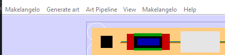
This is the harmonic gearbox we sell as individuals or in a 6-pack to make the Sixi 3 robot arm. At ten minutes each, you can have your entire arm assembled and ready in under 2 hours.
To describe the mood here this week in a word it would be “challenged”. My productivity is greatly affected by the all-grey of Vancouver winters – I can’t work if I’m not happy and it takes a lot more time to find my happy place each day in the winter.
How (and why) be a Makelangelo Tester
Not too long ago, with the help of the Marlin 3D printer firmware team, I managed to switch to Marlin. This was a huge time savings for me as I can now focus on making the software better. To make it great – for me, for you, for everyone – as fast as possible I need to shorten the cycle time – the time it takes to check a new feature works right.
Maybe you’ve noticed the app is missing something you need. Maybe you found a bug. Now for a lot of programs out there the way to tell them about a bug is not obvious, hard to achieve, and the turnaround time is … who knows.
I want to make a great app and put new issues to bed quick-fast. To me, the report-fix-test loop should be as short and fast as can be. I hope you agree! That is why I’m asking you to help me help you. Become a tester: to shorten the loop.
Report
With our without being a tester, the process starts by going to the Makelangelo code project and filing a good bug report. The bug report comes with a template to fill out that should make writing your report painless.
Fix
Then I or some other brave soul will (maybe) ask follow up question and (definitely) work to make the thing happen. Some are easier than others in surprising ways.
Test
Now this is the sticky part of the loop. When I write code I bang away in the magic language of the drow elves, cursed to roam the underdark. When the machine says I have atoned enough, it produces a jar file. This is then packaged with other essentials like the README file and somehow delivered to you to give it a little run-see, a little double sanity check, a thumbs up or down.
The packaging and delivery process is slow. So slow. In a more perfect world you should be able to say “get me the latest update from Dan!” and moments later be able to run it. Two clicks, right? Well friends, read on.
Thank you
Making it easy to make you happy is … it’s the greatest gift. A win/win. Thank you. It’s very easy to get lost in the weeds with code, and your input gives me clear focus and direction.
Special shout out to CaptFuture, Headly, and OopsHeIsDead for being awesome contributors this week.
Final thoughts
Here’s a gallery of recent Makelangelo Software updates to the app. Many of these changes were brought about by you and yours. I’ll continue to write, you continue to stay awesome. Until next week, be well!
Assuming you have two stepper motors, two limit switches, some timing belt, a 3D printer control board, and a hobby servo then you have everything you need to make a wall hanging plotter of your own that will work with Makelangelo Software. Read on for firmware configuration.
All the changes described herein have been applied to the fork of Marlin we maintain on Github. Make sure you are working with the branch called 2.1.x-polargraph which should match this blog post. You can modify this setup for your custom board. Many people have successfully built RAMPS+mega derivatives and shared their success stories in the Discord channel.
The main files we’ll touch are Marlin\Configuration.h and Marlin\Configuration_adv.h. First I will show the line to find and then explain what is changed and why.
Marlin\Configuration.h
#define MOTHERBOARD BOARD_RAMPS_14_EFB
This sets the type of brain board you are using. The full list can be found in Marlin\src\pins\pins.h. In my case I change BOARD_RAMPS_14_EFB to BOARD_RUMBA.
#define CUSTOM_MACHINE_NAME "3D Printer"
Change 3D Printer to Polargraph. It’s aesthetic and non-essential.
#define EXTRUDERS 1
Polargraphs have no extruders. Change 1 to 0.
//#define POLARGRAPH
I remove the // part in front of # so that it becomes defined.
These are the digital pins that are connected to your limit switches, uses for homing. When homing the machine will move the pen down and the counterweights up until the weights touch the switches. That is the maximum reach of each belt, and thus the max limit switch. For most boards, including RAMPS, you can ignore these lines so long as your switches are wired to x max and y max, respectively. These are here because RUMBA usage for polargraph predates Marlin adoption and Marlin needed to be made backward compatible for all existing customers.
I enable using maximum limit switch by removing the // at the start of these lines.
#define X_MAX_ENDSTOP_INVERTING true // Set to true to invert the logic of the endstop.
#define Y_MAX_ENDSTOP_INVERTING true // Set to true to invert the logic of the endstop.
#define Z_MAX_ENDSTOP_INVERTING true // Set to true to invert the logic of the endstop.
I have switches wired to go LOW when they are clicked. If you have it the opposite then you’ll want to leave these set to false.
#define E0_DRIVER_TYPE A4988
There is no E0 Driver and the sanity checks in Marlin will get mad if this is defined. Put another // at the start of the line.
There are only three axies of motion on this system, so we have to change it from { 80, 80, 400, 500 } to { 80, 80, 80 }. That assumes 200 step-per-turn motors and a 20 tooth GT2 pulley at 1/16 microstepping. (200*16) / (20*2)=80. Adjust your numbers accordingly. a 400-step motor would be 160 for the first two. The third is not really important because we don’t use a third stepper motor. Marlin won’t let me set two axies so it dangles on the end there like a vestigial tail.
#define DEFAULT_MAX_FEEDRATE { 300, 300, 5, 25 }
I have changed these to { 90*60, 90*60, 90*60 }. Experiment with this number and see what kind of speeds you can get!
I set mine to { 40*60, 40*60, 40*60 }. Another area I encourage you to experiment.
//#define CLASSIC_JERK
I don’t remember why I had to remove the // part but I did to appease the sanity checks.
#define INVERT_X_DIR false
By default Makelangelos are built with the left motor physically wired backwards so that “pull in” and “push out” was the same for both. So I have to change false to true. Discord user CaptFuture pointed out if you are building a DIY machine be aware mixing the wiring and the inversion might make some motors behave backwards.
//#define NO_MOTION_BEFORE_HOMING // Inhibit movement until all axes have been homed.
//#define HOME_AFTER_DEACTIVATE   // Require rehoming after steppers are deactivated.
I removed // from both. Safety third, right after chainsaws and LSD.
I changed these to 1 so that it homes to the maximum limits.
#define X_BED_SIZE 200
#define Y_BED_SIZE 200
Here I set the X_BED_SIZE to the width of a Makelangelo. The width is measured from one motor shaft center to the other motor shaft center. Makelangelo 5 is 650mm. For the Makelangelo height I used 1000mm (1m). More on this in a minute. Note: this number cannot be an odd number.
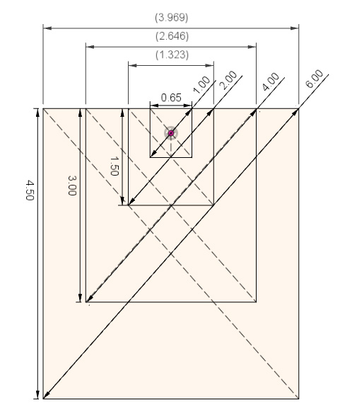
Remember using the triangle adjacent and the opposite to get the hypoteneuse? well here we use the opposite (machine bed size) and the hypoteneuse (the belt length) to get the adjacent, and then adjust by the Y_MAX_POS.
Image courtesy of Discord user PO
Note that the final value has to be inside the allowable drawing area of the machine – you can’t home to a spot that’s outside the printable area. That means the -Y_BED_SIZE/2 has to be a larger negative number than the MANUAL_Y_HOME_POS. With my settings -Y_BED_SIZE/2 is -500 and everything is fine.
//#define EEPROM_SETTINGS
remove the //. EEPROM_SETTINGS will allow you to tweak some firmware settings like acceleration and steps/mm from the LCD panel and then save them to the printer’s (very tiny) memory. Worth it!
//#define SDSUPPORT
If you have an SD card slot, remove the //.
//#define NUM_SERVOS 3
I set this to 1. As Jack Black said, one’s all you need.
//#define DEACTIVATE_SERVOS_AFTER_MOVE
Remove the //. This keeps the servo from jittering when not being used, which makes for a more pleasant sounding machine. It is reactivated every time it is used, don’t worry.
I changed to { 50*60, 50*60, 4*60 }. Three axis! THREE.
#define G0_FEEDRATE 3000 // (mm/min)
I changed the number to 12000. What can I say? I like to go fast.
LCD panels
Discord member Headly pointed out that there’s no mention of LCD control panels. Search Configuration.h for “LCD / Controller Selection” and then start reading. There are many choices from which to choose. For Makelangelo I use
#define REPRAP_DISCOUNT_SMART_CONTROLLER
If your Makelangelo has no LCD panel you must DISABLE this feature. When the robot is told to change pens (Gcode M0) it will wait for the user to click the dial. With no dial and no LCD, the user will be confused while the robot patiently waits forever.
While the previous Makelangelo-firmware talked at 57600 Baud, Marlin defaults to 250000. If you connect the app to your firmware and nothing is “heard” from the robot then the app and the robot are on two different baud rates.
Discord member Mesut asked about the minimum temperature settings in Marlin. There is no extruder so minimum temp settings are ignored by Marlin.
Help! Every G0 move goes to center!
Most motherboards that run Marlin have a small amount of EEPROM memory that needs to be initialized once to hold tweakable settings like top speed and machine dimensions. By default they are all zero, which makes math fail in the firmware and sends the pen holder to 0,0 on every move.
If you have an LCD panel connected to your machine the firmware should request a firmware reset at startup.
Another way is to connect over serial and send two commands: Reinitialize your EEPROM with an M502 factory reset, then save your EEPROM changes with an M500. Recheck that your machine width and height is not zero with an M503.
Custom hardware and DEFAULT_AXIS_STEPS_PER_UNIT
If you are building a custom machine, be aware that there are more settings to check. The DEFAULT_AXIS_STEPS_PER_UNIT is calculated this way:
( motor total steps per turn * microstepping ) / ( pulley pitch circumference )
Makelangelo uses 200 steps-per-turn motors and 16 microsteps. The pulleys are 20 tooth GT2 pulleys, or 40mm pitch circumference. That means our math is 200 * 16 / 20 or 80 steps per unit.
Be sure to check that your microstepping switches/jumpers match your math!
Final thoughts
After all these changes you should be able to upload the firmware and start running your polargraph drawing robot. Take it in small steps – try homing your machine with no belts on and then touch the switches to see if it behaves. Also check the pulleys turn the correct direction before putting the belts on.
By default Makelangelo software uses a servo position of 90 (middle of the range) for pen up and 40 for pen down. Keep that in mind when you install the servo horn (the finger thing that lifts).
If you have any trouble with this, please join me and other polagraph fans on the Discord channel. It may be you’re doing something exotic; maybe this document needs a refresh; or you just want to find people with similar tastes. Join us!
Discord is a popular online service for gaming that really took off during the 2020’s pandemic. My friends and I play Dungeons and Dragons and we wanted a way to roll dice online without giving all our data to some wierdo company. So, being that I’m good with code, I wrote my own. Here’s my steps so that you can learn from what I did. We’re also going to use a really powerful tool called regular expressions to make reading dice requests super easy.
On the shoulders of giants
Writing my own code from scratch and figuring things out is fun and educational, but I’m getting old and I don’t have a lot of time left. To save time I used Java, available libraries, and a slightly out of date tutorial by Oliy Barrett. I recommend you read this for the basics.
Hello, World!
When using someone else’s library there’s always a bit of setup and teardown. Here’s the essentials.
token.txt is the private token for this bot. Never share it. If you check it into Github then Discord will send you a friendly email telling you the token has been rejected forever and you have to make a new one. use your .gitignore to make sure that never happens.
public class DiscordDND extends ListenerAdapter {
    static final String MY_ENTITY_ID = "***";
    static final String MY_ENTITY_NAME = "Dice Roller";
    static public final String ROLL_COMMAND = "~r";

    public static void main( String[] args ) throws LoginException {
        String token = readAllBytesFromFile(DiscordDND.class.getResource("token.txt"));
        JDA jda = JDABuilder.createDefault(token).build();
        jda.addEventListener(new DiscordDND());
    }

    private static String readAllBytesFromFile(URL filePath) {
        String content = "";
        try {
            System.out.println("Token search: "+filePath.toURI());
            content = new String ( Files.readAllBytes( Paths.get( filePath.toURI() ) ) );
        }  catch (Exception e) {
            e.printStackTrace();
	}
        return content;
    }

    @Override
    public void onMessageReceived(MessageReceivedEvent event) {
    	if(event.getAuthor().isBot()) return;

    	String message = event.getMessage().getContentDisplay();

    	if(!message.startsWith(ROLL_COMMAND)) return;
    	// remove the prefix and continue
    	message = message.substring(ROLL_COMMAND.length());

        System.out.println("I heard: "+message);

        // handle the roll here
    }
}
When the app runs it loads the token, connects to Discord with the token, and gets ready to listen to things being said in the discord servers to which it has been invited. How do you invite a bot to a server? Uh… I don’t remember.
Understanding a roll request
The regular expression syntax for a dnd dice roll
The normal format for writing out a dice roll in DND is [number of dice]d(number of sides)[k(number to keep)][+/-(modifier)] with no spaces. I found a regular expression online that pretty closely matches this pattern and modified it.
Anything in a () is a group.
? means “zero or one of the previous element” (in this case, the previous group).
[\+\-] means “any characters inside the [] braces”. Combined with the ? it means “at most one + or – symbol.” Because of text formatting rules in regular expressions the + and - have to escaped by putting a backslash \ in front of them.
\d means digit. \d+ means 1 or more digits.
So putting it all together it says:
The first group has a positive or negative whole number. The group is optional.
The second group starts with the letter ‘d’, then a positive or negative whole number. The group is required.
The third group starts with the letter ‘k’ and then a positive or negative whole number. The group is optional.
The fourth group MUST start with +/- and then a whole number. The group is optional.
Hey! Why negative dice and negative sides? It’s not that I want negative dice. But sometimes users type silly things. I thought it would be fun to catch those and deal with them in equally funny ways.
Why keep negative dice? In DND sometimes the player rolls with advantage to keep the highest dice and sometimes they roll with disadvantage to keep the lowest dice. Negative numbers mean keep the low dice.
To use regular expressions in Java (or OpenJDK) I’m using the Pattern and Matcher classes.
// remove all whitespace and the roll command from the start
String saneMessage = sanitizeMessage(event.message);

Pattern p = Pattern.compile("([\\+\\-]?\\d+)?(d[\\+\\-]?\\d+)(k[\\+\\-]?\\d+)?([\\+\\-]\\d+)?");
Matcher m = p.matcher(saneMessage);
id(m.find()) {
	int numDice=1, numSides=20, numKeep, modifier=0;
	if(m.group(1) !=null && !m.group(1).isEmpty()) numDice  = Integer.parseInt(m.group(1));
	if(m.group(2) !=null && !m.group(2).isEmpty()) numSides = Integer.parseInt(m.group(2).substring(1));
	if(m.group(3) !=null && !m.group(3).isEmpty()) numKeep  = Integer.parseInt(m.group(3).substring(1));
	else numKeep=numDice;
	if(m.group(4) !=null && !m.group(4).isEmpty()) modifier = Integer.parseInt(m.group(4));

	roll(event,numDice,numSides,numKeep,modifier);
	return;
}
In Java Strings the \ symbol is special so I have to escape them again – the double backslash is not a mistake.
Matcher returns the original expression in m.group(0). If Matcher does not find a group it returns null for that group index. That means I can reliably expect group 4 is always the modifier and so on.
The catch here is that I don’t want to sort the rolls into high > low because it would look wrong to the user. Organic rolls do not happen that way! I’m stuck searching for the worst roll, numRolls – numKeep times.
for(int k = numKeep;k<rolls.length;++k) {
	int worst = 0;
	for(int i=0;i<rolls.length;++i) {
		if(rolls[i]>0 && rolls[worst]>rolls[i]) worst = i;
	}
	rolls[worst] *= -1;  // mark it as rejected but keep the value.
}
Final thoughts
As a final bit of flair I add a meme pic for natural 20 and natural 1 rolls. If a natural 1 is not kept I put in Neo’s famous bullet dodge from The Matrix. What would be a good meme for a not-kept-natural-20?
In this video I’ll show you how to model straight GT2-6 timing belt and how to model continuous belt around two pulleys in a plane.
The centre to centre distance
When modelling a belt around two pulleys we have a few constraints:
the pitch circumference of each pulley
the pitch of the timing belt
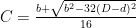
What we need is the ideal distance between the centre of the two pulleys so that the belt fits perfectly. The centre to centre distance is described as
C = center to center distance
D = diameter of pitch circle of gear 1
d = diameter of pitch circle of gear 2
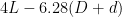
b =
L = pitch of timing belt
For Fusion 360 you may find that it is easier to break the large equation into smaller sections like calculating ‘b’ first.
Final thoughts
Should I do a follow up with other kinds of belt? Other designs? Let me know.