Hey, gang! Here is what we worked on in the last week, where we are heading next, and how you can join us.
Welcome Jacob & Scott
We have new interns! Our factory grows! Mwhahahahaha~! I get these two bright young men for three whole weeks and I am working them tirelessly to breaking beneath the unforgiving whip of industry on every project that we’ve been saving as “great if we had more unfiltered evil time”.
Among their first tasks has been converting some of the STL files we use into Fusion 360 versions so that we can tweak them; testing parts they designed;
practicing their maniacal laughter; and repairing a 3D printer that has an unfortunate accident…
New Dozuki Process Control
Scott & Jacob have also been building new documentation for our team, DIYers, and new users. Documenting our process means more control and better quality. I love Dozuki ever since I saw it used by Prusa Printers. Check out the start of our documentation.
Sixi Robot Arm Anchor and Shoulder First Look
Yes! The first version of the anchor and the shoulder have been birthed from the primordial ooze printed. As soon as omc-stepperonline.com come back from Lunar New Years and ship our parts (we expect delivery ~the 20th) then we’ll be putting it together and finally conquering the planet making it move.
Get Educated
I’m back in school to up my game!
First off, Mandarin. I keep ordering fancy parts from China and I hear all the best deals are on chinese-only sites like Taobao. It is easier to convince people that robots are the future if I speak their language. One in six people understands Mandarin so it’s the obvious choice.
Second off, professional Machinist courses. I’ve signed up to take CNC lathe work at BCIT and their classroom is a machine porn wet dream.
Next
Next week we have a scheduled power outage for another electrical upgrade to the super ray. I plan to spend the time at Vancouver’s Science World wreaking havoc filming footage for a new Makelangelo video. We don’t plan to be there more than once for this, so I’m drawing schemes storyboards for the first time. Nice!
You can use this file to build your own copy of the robot arm. Put that 3D printer you bought to use – Make it your own! Share your creation with others! That’s what open source is about. If you build one we would love to share it with others. I am actively seeking talent… show me what you got.
As always, follow our daily progress on our Instagram or see our older stuff on Youtube.
Lastly, thank you for your likes, subscribes, comments, and purchases. You keep the lights on and the mood high so we can keep working on awesome things that will help the planet.
Special thanks to Bernie at Coast Precision CNC that saw my broken printer Instagram post and offered me one of his spare thermistors. We were back up and running the same day! Excellent.
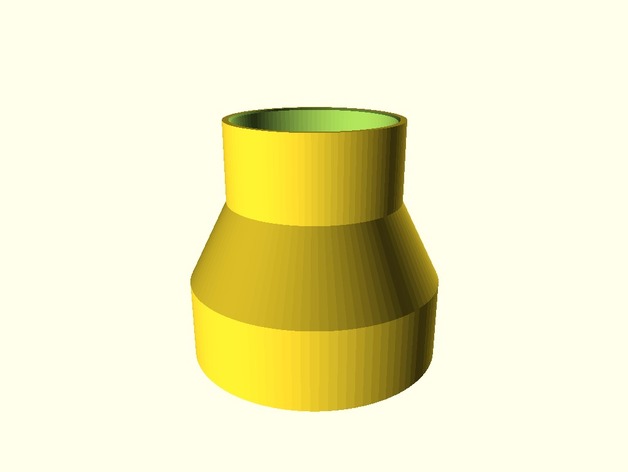
Recently a good friend asked me to make an adapter to connect the air hose from his vacuum to the air hose on his new scroll saw. Both were, obviously different sizes. 3D printing to the rescue!
Shortly after he went home happy, I was thinking it would be great to have a tool that solves this problem forever. Thingiverse has an option to make customizable, parametric designs. So I whipped out SCAD modelling program and in about an hour crafted this tool that is free for everyone.
You can change the diameter of the two hose ends, how far the hose ends sink into the adapter, and the thickness of the walls. There is a small lip inside the shape to keep the hose from moving too far into the adapter.
In the first two weeks it has been remixed ten times already. Fantastic! If you find it useful, please tag me online or join my Patreon.
Here is a comprehensive list of all the gcode understood by the Makelangelo firmware. Please use this guide to create your own gcode generator, to understand the gcode created by Makelangelo software, or to build machines that comply with the format.
Gcode commands should be common to most CNC machines and follow the same format as 3D printers, mills, lathes, and others. For a more complete reference, please visit https://en.wikipedia.org/wiki/G-code. Wherever possible we have tried to match the format.
Command structure
All commands are on separate lines (one command per line). All lines end with a newline (\n). A return (\r) is not required. Blank lines are ignored. Any text after a ; is ignored. This gives you room to add comments inside a list of gcode commands. Commands can be preceeded by a line number:
N[n] command;[checksum]
where [n] is some number >= 0 and checksum is a non-printable character (the XOR sum of all previous characters in the command, not including line number and semi-colon ‘;’ ). Every correctly parsed command with a line number will increment the expected line number.
M Commands
M6 T[n] Change to tool number [n].
M17 Engage (turn on) all motors. They will actively resist being moved and will obey commands.
M18 Disengage (turn off) all motors. They will not resist being moved and will ignore commands.
M20 List files on SD card (if any) to the serial connection.
M42 P[n1] S[n2] Change digital pin number [n1] to state [n2] (0 for low voltage, 1 for high voltage)
M100 Print help message to the serial connection.
M101 A[n1] T[n2] B[n3] Change software limits for axis [n1] to max/top [n2] and minimum/bottom [n3]. These limits are in millimeters.
M102 Print machine axis limits to the serial connection.
M110 N[n] Change the next expected line number to number [n]. This means that the N[n] can appear twice on a single line with different values. The firmware should treat the first N as the current line number and the second N as the desired line number.
M114 Report the current state of the machine to the serial connection. This includes where it believes it is positioned, the feed rate, the acceleration, and possibly other values.
M117 [string] Display messsage [string] on the LCD panel.
M226 P[n1] S[n2] Wait for digital pin number [n1] to be in state [n2] (0 for off, 1 for on). If P is not included, the default is the LCD button pin. If S is not included, the default is off (0).
M300 P[n1] S[n2] Play frequency [n2] for [n1] milliseconds through the LCD speaker. If P is not included, the default is 250 (1/4s). If S is not included, the default is 60 (a C note). Some buzzers cannot play different frequencies.
G commands
G0 X[n1] Y[n2] Z[n3] U[n4] V[n5] W[n6] A[n7] F[n8] G1 X[n1] Y[n2] Z[n3] U[n4] V[n5] W[n6] A[n7] F[n8] Move the machine in a straight line to (X,Y,Z,U,V,W) at feedrate F and acceleration A. All values are millimetres, except F and A which are in motor steps per second. If any of these parameters are not included, the current value is used.
G2 X[n1] Y[n2] I[n3] J[n4] A[n5] F[n6] G3 X[n1] Y[n2] I[n3] J[n4] A[n5] F[n6] Move the machine in an an arc around a circle in the XY plane. The arc begins at the current position. The arc ends at (n1,n2). The center of the circle of the arc is (n3,n4). G2 is for clockwise arcs. G3 is for counter-clockwise arcs. If any of these values are not included, the value is unchanged. I and J default to X and Y, respectively.
G4 P[n1] S[n2] Dwell (wait) for n1 seconds and n2 milliseconds.
G28 Find home. This is different for each machine design. In general this means that the machine moves until it activates sensors to confirm its position. Many machines will refuse other G commands until G28 is completed. G28 is not run automatically when the robot turns for human safety.
G54 X[n1] Y[n2] Z[n3] U[n4] V[n5] W[n6] Adjust tool offset for tool 0. This way the position the machine will report is the same as the position at the tip of the tool.
G55-G59 Adjust tool offset for tools 1-5. See G54 for more information.
G90 Absolute movement mode. All movement position values are relative to the machine’s frame of reference.
G91 Relative movement mode. All movement position values are relative to the current position.
G92 X[n1] Y[n2] Z[n3] U[n4] V[n5] W[n6] Adjust the machine’s internal position value.
Non-standard Gcode Commands
The following commands are unique to Makelangelo firmware. They will not appear in other machines.
UID [n] Set the robot’s unique id number to [n].
D0 L[n1] R[n2] U[n3] V[n4] W[n5] T[n6] Jog motors. Each letter represents a different motor. each [n] is a number of steps to move. the number of steps can be negative for a reverse jog. Not all machines have one motor per axis.
D4 [string] Begin processing the file on the SD card called [string].
D5 Report firmware version number.
D6 X[n1] Y[n2] Z[n3] U[n4] V[n5] W[n6] Set home position for each axis. When G28 completes the machine will teleport (G92) to this position.
D7 [Lnnn] [Rnnn] Adjust Makelangelo calibration values for the length of left and right belts. Default is 1011mm.
D8 Report Makelangelo calibration values for left and right belts
D9 Save Makelangelo calibration values for left and right belts.
D10 Print hardware version number to the serial connection.
D11 Set up all default values for the Makelangelo 5.
D12 Assume the robot is as machine reference (absolute) position 0 on each axis. Move towards home switches and measure the distance. Then adjust D6 based on the measured distance.
D13 Adjust the pen angle on the Makelangelo. This is the same as a jog command. it is always absolute position in degrees.
D14 Report the machine style (kinematic model) to the serial connection.
It would be easy to set a camera next to the printer, set a fixed time lapse between shots, and let it run the while the printer does what it do…. but I want better than that: I want the time lapse to show the growing shape to be the only moving thing in the shot and the printer moves as little as possible. The difference is intense.
Without printer stabilization
With printer stabilization
This is done with Raspberry Pi that will control both the 3D printer and the web camera. So enough talk, let’s get to it.
Follow the steps in the above video until the 6:45 mark.
Settings > Software Update > Update All. Restart Octoprint when it requests and surf back to the page.
Settings > Plugin Manager > Get More… > Search: OctoLapse > Install. I had to be very patient here. The download was fast, the install took nearly an hour on a Pi B+. Eventually Restart Octoprint when it requests and surf back to the page. The top will now say OCTOLAPSE instead of OctoPrint. The Octolapse settings will be hidden in a drop-down menu on the top right, under the user login. Set your Printer and Stabilization settings. I chose Back Right because my camera is front left.
This picture was taken during a timelapse. Some details may differ.
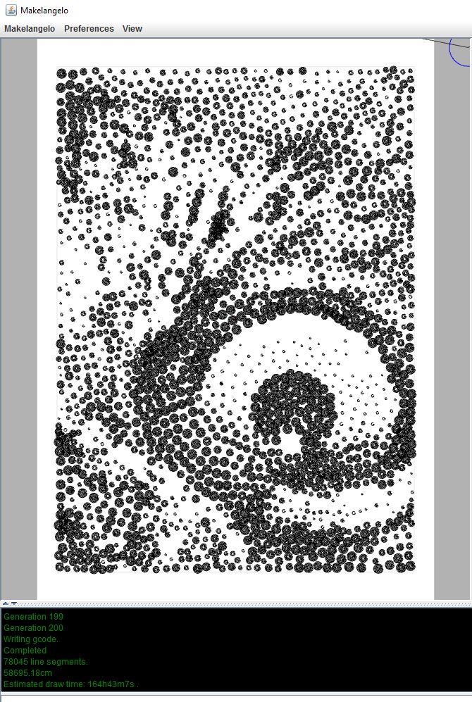
In Octoprint web panel expand the left side Files box and click Upload. Not Upload to SD! Choose the gcode file you saved to your computer.
To the right of Files is a wrench. Click it and “sort by upload date (descending)”. Your new file will be at the top of the list of files, which will include whatever is on your Prusa’s SD card. Timelapses will not be perfect if done from the SD card. They must be uploaded to the Pi so that the Pi (octolapse) can inject the gcode to move the printer when it’s time to take a photo.
Hit print!
Time lapse results
It looks pretty good! For better results I will move the filament out of the shot, add a backdrop to hide irrelevant noise, and maybe play with a better camera angle. Surely Mr. Robot Guy can build a rail for a panning time lapse, right?