robot arms in Robot Overlord
News

Friday Facts 11: How to add a robot arm to Robot Overlord (2022)

Robot Overlord is going to be the inkscape, the VLC, the Steam of robot arms – the one vendor-agnostic interface everyone teaches, knows, and loves. In order to get there it has to support every robot arm under the sun. This post is for robot arm makers that want to save time by not writing all their own code.

Some of the arms already available

Did you know Robot Overlord speaks natively to Marlin 3D printer firmware? Save even more time by using the same firmware.

You will need

  • A 3D CAD model of your robot arm
  • The D-H parameters of the arm in the same pose as it appears in your CAD file
  • The ability to write Java code for the Robot Overlord project
  • Some familiarity with git (forks, commits, pull requests)

Prepare your CAD file

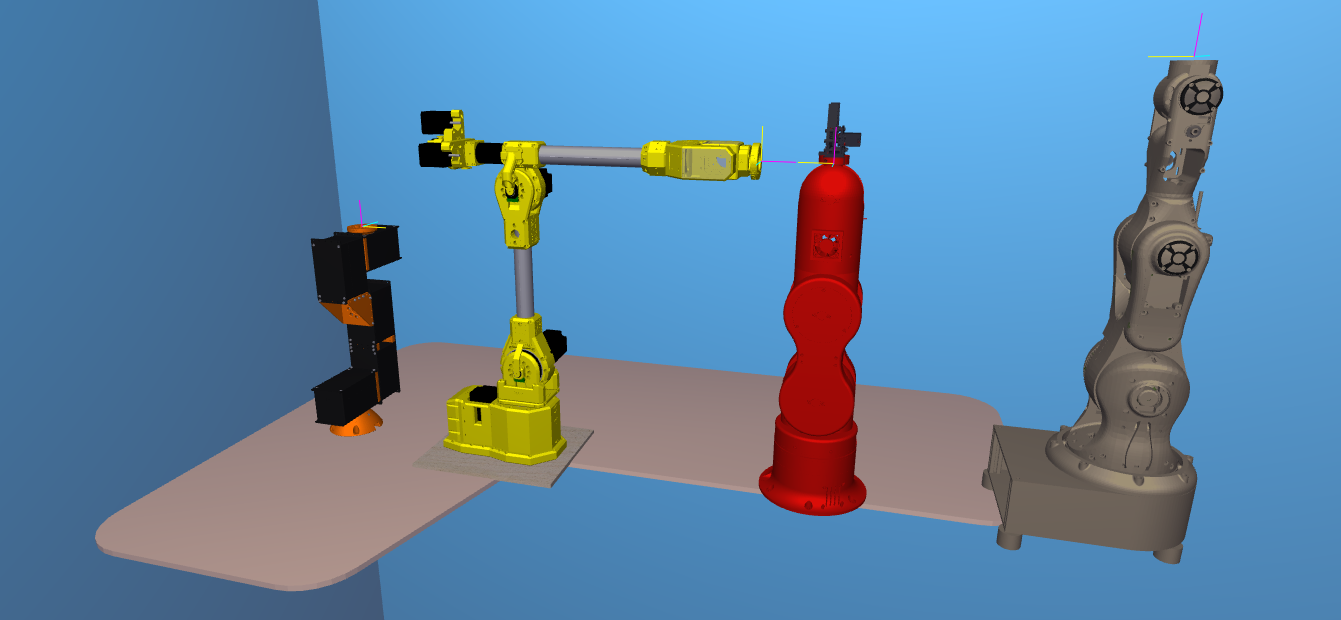
It is easiest to export your arm into discrete moving sections, all of which with the same origin at the bottom center of the base of the arm (see slide 1). This is the same origin as the D-H parameters.

A meca500 robot, color coded with the base and six parts. the origin would be in the red part, on the same axis of rotation as the pink part

To help Robot Overlord run smoothly and to protect your IP it is recommended that you decimate the model by removing all hidden internal structures and components. Consider leaving screw heads while removing the threaded sections to save many megabytes of file size.

Each discrete section should be exported as an OBJ or STL file. (more on this later.)

The exported files should be located in /src/main/resources/[your robot folder]/. So if your robot is named Foo then it would be /src/main/resources/foo/. It would be consistent to name them base, j0, j1, etc.

Prepare your Robot Overlord class

In Robot Overlord’s /src/main/java/com/marginallyclever/robotOverlord/robots/robotArm/implementations you will find the collection of currently supported robot arms. It may be easiest to copy one of these classes and modify it for your purposes. Here is the minimum needed to code your arm. Every instance of Foo should be replaced with your class name.

public class Foo extends RobotArmIK {
	private static final long serialVersionUID = 1L;

	public Foo() {
		super();
		setName("Foo v1");  // the name that appears to users.
	}
	
	@Override
	protected void loadModel() {
		setBaseShape(new Shape("Base","/Foo/j0.obj"));

		// The DH parameters and the model file, added in order from J0 ... J5.  
		// angles are degrees, distances are centimeters.
		// name d r alpha theta thetaMax thetaMin modelFile
		addBone(new RobotArmBone("X", 7.974,     0,270,  0,170,-170,"/Foo/j1.obj"));
		addBone(new RobotArmBone("Y", 9.131,17.889,  0,270,370, 170,"/Foo/j2.obj"));
		addBone(new RobotArmBone("Z",     0,12.435,  0,  0,150,-150,"/Foo/j3.obj"));
		addBone(new RobotArmBone("U",     0,     0,270,270,440, 100,"/Foo/j4-6.obj"));
		addBone(new RobotArmBone("V",15.616,     0, 90, 90,270,-90,"/Foo/j5-6.obj"));
		addBone(new RobotArmBone("W",  5.12,     0,  0, 180,360,   0,"/Foo/j6-6.obj"));

		adjustModelOriginsToDHLinks();
		setTextureFilename("/Foo/texture.png");
	}
}

Now that the arm can be loaded by the app it needs to be on the menu of things that can be created by the user. In /src/main/java/com/marginallyclever/robotOverlord/EntityFactory.java add your new class:

public class EntityFactory {
	private static Class<?> [] available = {
		// ...
		com.marginallyclever.robotOverlord.robots.robotArm.implementations.Mantis.class,
		com.marginallyclever.robotOverlord.robots.robotArm.implementations.Sixi2.class,
		com.marginallyclever.robotOverlord.robots.robotArm.implementations.Sixi3_5axis.class,
		com.marginallyclever.robotOverlord.robots.robotArm.implementations.Sixi3_6axis.class,
		com.marginallyclever.robotOverlord.robots.robotArm.implementations.Thor.class,
		com.marginallyclever.robotOverlord.robots.robotArm.implementations.Foo.class,  // "Foo" must be your class name.
	};
	// ...
}

Now when you run the application and open the Add menu your robot name will appear.

‘Foo v1’ will appear on this list

Model size and orientation fixes

It is possible that your model appears in Robot Overlord too large, too small, or the parts are rotated in a strange way. My solution is to use a modelling program like Blender to rotate, scale, decimate, and even texture the model.

Forward and Up will control the rotation. +Z is always up in a Robot Overlord scene.

Selection Only will simplify your exporting from Blender. In the image above it will only export J2.

Scale will control the size. For models that appear in meters instead of centimeters, choose 0.1. If your model is imperial, you’ll probably want 2.54.

Now share it with …the world!

You’ve changed the code, you’ve massaged the model, it runs on your machine. Now to share it with everyone else! A pull request from you to the Robot Overlord project will tell the dev team that your stuff is ready. This is the best way to make sure your model gets in the way you want it.

No time? Let us do it for you.

We can add your model(s) to our system. Contact us! We’re looking to collaborate and work with everyone. Writing the class is free; preparing the CAD files is specialized work we outsource and will quote.

What about URDF files?

URDF is the Unified Robot Description Format, part of ROS, the Robot Operating System. ROS is a nice system but much harder to get running – part of the reason I work on Robot Overlord. Join the Robot Overlord github project and help make it happen? Imagine what we could do together!

News

Friday Facts 9: Daisy Stepper Driver 1.0

Daisy Stepper Driver is a closed-loop stepper controller that can be daisy-chained.

A stepper controller is a dual h-bridge circuit for controlling a stepper motor. You may be familiar with the A4988 stepper driver common in 2020s 3D printers. This board includes a more advanced model of the same. It can drive any one stepper motor at 24V up to 2A.

Closed-loop means that the board has a brain chip (MCU) that can read the motor position as well as direct. This way it can tell if it missed a step, bumped into something, is being driven, etc.

Daisy-chained means that they can be hooked sequentially. Sequential wires are much shorter. Shorter wires make for easier construction and repair. They are designed for up to 6 Daisies in a row. The Daisies talk to each other via the CANopen protocol.

The MCU is an STM32F103. In speaks CANopen natively while driving the stepper and listening to the sensor.

The CANopen master at the base of the robot can be any MCU that speaks CANopen. It synchronizes each motor and provides a single USB or bluetooth serial connection to the world.

What does this have to do with robots?

This board is designed to fit inside each gearbox of the Sixi 3 robot arm.

The old way a wire from every part had to run all the way through the arm and out the base. To replace the second joint from the bottom you would have to dismantle the entire arm. In the daisy chain model you only need to remove the elbow and disconnect the two cables to the next link in the chain.

Here’s a video of the arm moving IRL. Note the large cable hanging off the side – this version does not have the board in yet. It is the “outside” version of the wiring. I live in constant anxiety that they will get caught on something while moving.

Editor’s note – in this video one motor misbehaves. It was later found that the motor was negative 400-steps per turn instead of the expected 200-steps-per-turn.

Why isn’t the board in already?!

To test the board I have to be able to program it. To program the STM32F103 MCU I need to flash it with a bootloader via the programming pin J6. I have an STLINK V3 MINI to flash the bootloader BUT the MINI has male pins at 1.25mm pitch and my board’s J6 is 2.5mm pitch.

Editor’s note – I believe the larger connector is also a reversible connector.

Do you want to see this board get done? Say something nice on Discord.

What comes next?

Assuming this board is good and can be programmed… the next tasks are:

  • mount the board in the actuator
  • attach the disc to the output of the gearbox
  • run wires from one to the next and test the daisy chain
  • get an appropriate brain board and drive everything synchronously
  • make more boards

At the last stage it will be time to go to Kickstarter to scale production and bring the price down.

Did you design this board yourself?

No, and I’m proud of it! I have played with KiCAD in the past and done a few but this was beyond my skill. I found a great EE on Fiverr, gave him my specs, and he routed everything in a couple of days. Truly blown away by his skill. He even had a PDF step-by-step guide for ordering from PCBWay so I didn’t have to assemble the board or nothing.

Sadly, he closed his account and I have no way to reach him any more. Electroniikka! If you’re out there, know that I want to work with you again. I love working with talented people, it’s fun, easy, and it helps me scale up to the speed I long for.

News

Friday Facts 8: Plotting large sewing patterns

Here’s a use for Makelangelo plotters that I never considered, offered up by Discord member Jolo: Sewing patterns for home sewing, cosplay and costume design!

It turns out that there’s many free pattern sites. Here’s just one example of a hoodie.

I used Freesewing.org to get a pattern for a hoodie and then chose export pattern > SVG and saved to my desktop.

In Inkscape I opened the file, set the document size to A2 and used that as a guide to split up the file into sections that fit on the paper for the Makelangelo. Just to be cautious I used Object > Ungroup and Path > Object to Path to prevent any import questions. These might not be necessary, but I do them with my laser cutter and it’s a habit now.

I had to delete everything except the part on the paper for each export. Then I used Save As > DXF R14. Makelangelo also understands SVGs – another habit from my laser cutting work. (this post was not paid for by Big Laser – Ed)

Then I loaded it into Makelangelo software and drew it just like any other drawing.

Final thoughts

The HUGE extension for Makelangelo draws up to A0 (841 x 1188 mm aka 33-1/8 x 46-13/16 in)

Do you have other great uses for a large plotter? Share with us and we’ll share it with the world!

You might also get a kick out of open source, parametric pattern design app called Seamly.

News

Friday Facts 7: A 2D physics engine in Processing (Java) and the Sunk Cost Fallacy

I have a robot dog being operated on by the Students at Alpha Secondary school in Burnaby, BC, as part of a work experience program. The goal is to make the dog walk as good or better than Spot Micro. Obviously this is not done in a weekend. How do you eat an elephant? One piece at a time. The current plan is to tackle things in order:

  • get it to turn on (done!)
  • move each motor individually (done!)
  • move them together (done!)
  • make it stand up and sit down (working on it!)
  • teach it to roll over and recover from a fall
  • teach it to walk

In a sense I’ve delegated all these steps to the students. Which frees me to do the part that needs experience – making tools that will empower them to do the hard steps at the end.

I don’t want to break the robot because it’s expensive to fix. Therefore I don’t want anyone to drop the robot hundreds of times while testing it. Given the tools I have, what can I do to test the robot without dropping the robot? The same thing I’ve done with all my robots – simulate them! But I’ve never used a phsyics system in Robot Overlord before.

I already have all my code and development tools in Java, so my first instinct is to continue in that direction. I didn’t find any up-to-date physics engines that work in Java. JBullet hasn’t been updated since 2016. Other engines I found were Java ports of C libraries. I don’t have links to them any more but those I found were stale and had no “contact us” system. Two solutions present themselves:

  1. Write my own physics system in Robot Overlord from scratch
  2. Install Gazebo on a linux system, ?, profit.

For your consideration, this is my attempt at number 1.

2D physics with circles and boxes in Processing

This is the first time I’ve had to simulate things with physics in Java.

This is a 2D physics engine written in Processing 4.0b. At tag 1.0, it looks like this:

Much help and inspiration was obtained by reading the code for Impulse Engine by Randy Gaul. Do your homework!

It took a day to write the drawing of shapes and 13 more to debug the physics up to this point. Here’s what it looked like at the half-way point:

The hope is to extend this into 3D, add constraints (think bones connected by joints), add friction, and then make physically approximate ragdoll models of the Spot Mini. They can be dropped, kicked, drop kicked, and beat up over and over until the simulated walking gets them up and balanced. Then the simulation can be tied to the real machine and our goal should be within sight if not in reach.

The sunk cost fallacy

Initially I didn’t even consider option no 2. The cost of setting up a linux box or partition, learning Gazebo, installing the robot model, unknown further mysteries tbd… I choose the devil I know over the devil I don’t!

Discord user M2710 DM’d me to ask “why don’t you just [gazebo]?” and made a compelling case that it might be easier than running my own physics engine. I couldn’t immediately prove the idea wrong so I have to consider it might be right. I’ve booked a day in the near future to try Gazebo and Webots. Look for that in an upcoming FF.

Hiring

If you have experience with Gazebo or Webots, share your story with us on the Discord channel. we really want to eat your juicy brains know what you know.

If you have java/physics skills and you think you can get the Robot Overlord features (3D, constraints, friction, physically approximate ragdoll models of the Spot Mini) working, DM me! I want to help you help me. Make me an offer, I’m eager. I only have so many hours in the day and I need your help.