Makelangelo News

Makelangelo Software v7.17.0

Today I’m pleased to release Makelangelo Software v.7.17.0, the open source control program for our Makelangelo drawing robot.  This new version can now generate spirographs and read Scratch sketches.  Read on for all the details.

Minor improvements

First, some little details.  I’ve added a Help menu that contains the About tab and a link directly to the forums.

Makelangelo Spirographs

Generate Art > Spirograph will open the spirograph dialog and immediately generate the first spirograph.

By default the generator creates hypotrochoid drawings.  A hypotrochoid drawing is made by rolling a circle inside a ring, while keeping your pen at the same spot in the circle at all times.

Selecting epitrochoid will put the circle on the outside fo the ring.

The Major radius (R) value is the size of the ring.

The Minor radius (r) value is the size of the circle rolling around the ring.

The Scale (p) value is the distance from the center of the circle to the fixed point that the pen will follow.

The Sample (quality) increases the number of lines used to draw the shape.  More samples means smoother line.

Makelangelo Scratch Support

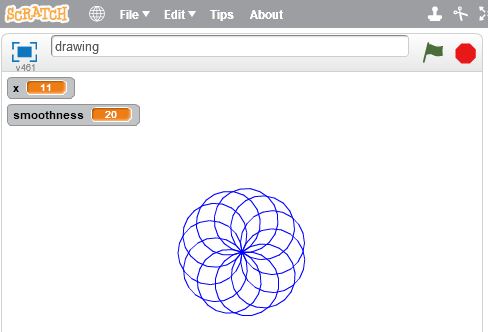
Scratch, from MIT, is the Minecraft of computer programming.  Each block does a different thing and blocks can only be combined in certain ways.

Supported scratch commands

The scratch program above, when run (by clicking the green flag icon, generates a kind of spirograph.  (Total coincidence.)

Scratch programs can be downloaded from the website to your computer

And then uploaded to the Makelangelo software.  Remember to change the file type to SB2

File > Open > Type = SB2

You should then immediately see the sketch drawn in the main view.

The extra lines are Makelangelos’s drawing of the pen holder

All scratch programs supported by Makelangelo Software v.7.17.0 must begin with a “When flag clicked” block.

Makelangelo Scratch (Scratchelangelo?) supports:

  • Move
  • Pen up/down
  • Turn and point in direction
  • Change x/y
  • Set x/y
  • Creating variables
  • Set variable to a number
  • Change variable by [operation]
  • Repeat [operation]
  • Hide, show, wait, and clear are ignored by Makelangelo and convenient for Scratch testing.
  • All other Scratch commands will probably cause an obscure error message.

There is no hard limit to the length of a sketch, the number of variables, or the complexity of a sketch.

As always, you can discuss these improvements in the forums.  We’d love to see what you make!

3D Printing Tutorials

Gcode Reference Guide

Here is a comprehensive list of all the gcode understood by the Makelangelo firmware.  Please use this guide to create your own gcode generator, to understand the gcode created by Makelangelo software, or to build machines that comply with the format.

Gcode commands should be common to most CNC machines and follow the same format as 3D printers, mills, lathes, and others.  For a more complete reference, please visit https://en.wikipedia.org/wiki/G-code.  Wherever possible we have tried to match the format.

Command structure

All commands are on separate lines (one command per line).  All lines end with a newline (\n). A return (\r) is not required.  Blank lines are ignored.
Any text after a ; is ignored. This gives you room to add comments inside a list of gcode commands.  Commands can be preceeded by a line number:

N[n] command;[checksum]

where [n] is some number >= 0 and checksum is a non-printable character (the XOR sum of all previous characters in the command, not including line number and semi-colon ‘;’ ).  Every correctly parsed command with a line number will increment the expected line number.

M Commands

M6 T[n]
Change to tool number [n].

M17
Engage (turn on) all motors. They will actively resist being moved and will obey commands.

M18
Disengage (turn off) all motors. They will not resist being moved and will ignore commands.

M20
List files on SD card (if any) to the serial connection.

M42 P[n1] S[n2]
Change digital pin number [n1] to state [n2] (0 for low voltage, 1 for high voltage)

M100
Print help message to the serial connection.

M101 A[n1] T[n2] B[n3]
Change software limits for axis [n1] to max/top [n2] and minimum/bottom [n3].  These limits are in millimeters.

M102
Print machine axis limits to the serial connection.

M110 N[n]
Change the next expected line number to number [n]. This means that the N[n] can appear twice on a single line with different values. The firmware should treat the first N as the current line number and the second N as the desired line number.

M114
Report the current state of the machine to the serial connection. This includes where it believes it is positioned, the feed rate, the acceleration, and possibly other values.

M117 [string]
Display messsage [string] on the LCD panel.

M226 P[n1] S[n2]
Wait for digital pin number [n1] to be in state [n2] (0 for off, 1 for on).
If P is not included, the default is the LCD button pin.
If S is not included, the default is off (0).

M300 P[n1] S[n2]
Play frequency [n2] for [n1] milliseconds through the LCD speaker.
If P is not included, the default is 250 (1/4s).
If S is not included, the default is 60 (a C note).
Some buzzers cannot play different frequencies.

G commands

G0 X[n1] Y[n2] Z[n3] U[n4] V[n5] W[n6] A[n7] F[n8]
G1 X[n1] Y[n2] Z[n3] U[n4] V[n5] W[n6] A[n7] F[n8]
Move the machine in a straight line to (X,Y,Z,U,V,W) at feedrate F and acceleration A.  All values are millimetres, except F and A which are in motor steps per second.  If any of these parameters are not included, the current value is used.

G2 X[n1] Y[n2] I[n3] J[n4] A[n5] F[n6]
G3 X[n1] Y[n2] I[n3] J[n4] A[n5] F[n6]
Move the machine in an an arc around a circle in the XY plane. The arc begins at the current position. The arc ends at (n1,n2).  The center of the circle of the arc is (n3,n4).  G2 is for clockwise arcs.  G3 is for counter-clockwise arcs.  If any of these values are not included, the value is unchanged.  I and J default to X and Y, respectively.

G4 P[n1] S[n2]
Dwell (wait) for n1 seconds and n2 milliseconds.

G28
Find home. This is different for each machine design. In general this means that the machine moves until it activates sensors to confirm its position. Many machines will refuse other G commands until G28 is completed. G28 is not run automatically when the robot turns for human safety.

G54 X[n1] Y[n2] Z[n3] U[n4] V[n5] W[n6]
Adjust tool offset for tool 0. This way the position the machine will report is the same as the position at the tip of the tool.

G55-G59
Adjust tool offset for tools 1-5. See G54 for more information.

G90
Absolute movement mode. All movement position values are relative to the machine’s frame of reference.

G91
Relative movement mode. All movement position values are relative to the current position.

G92 X[n1] Y[n2] Z[n3] U[n4] V[n5] W[n6]
Adjust the machine’s internal position value.

Non-standard Gcode Commands

The following commands are unique to Makelangelo firmware.  They will not appear in other machines.

UID [n]
Set the robot’s unique id number to [n].

D0 L[n1] R[n2] U[n3] V[n4] W[n5] T[n6]
Jog motors. Each letter represents a different motor. each [n] is a number of steps to move. the number of steps can be negative for a reverse jog. Not all machines have one motor per axis.

D4 [string]
Begin processing the file on the SD card called [string].

D5
Report firmware version number.

D6 X[n1] Y[n2] Z[n3] U[n4] V[n5] W[n6]
Set home position for each axis. When G28 completes the machine will teleport (G92) to this position.

D7 [Lnnn] [Rnnn]
Adjust Makelangelo calibration values for the length of left and right belts. Default is 1011mm.

D8
Report Makelangelo calibration values for left and right belts

D9
Save Makelangelo calibration values for left and right belts.

D10
Print hardware version number to the serial connection.

D11
Set up all default values for the Makelangelo 5.

D12
Assume the robot is as machine reference (absolute) position 0 on each axis. Move towards home switches and measure the distance. Then adjust D6 based on the measured distance.

D13
Adjust the pen angle on the Makelangelo. This is the same as a jog command. it is always absolute position in degrees.

D14
Report the machine style (kinematic model) to the serial connection.

Tutorials

Delta Robot 3 Assembly Manual

Delta Robot 3 uses three motors turned 60 degrees from each other to achieve XYZ translation motion.  It is most popularly known in the Kossel 3D printer.  You might have seen one of our robots at DEFCON being used to type out pin pad combinations to unlock a cell phone.

While we do not make the Delta Robot 3 at this time, we believe in open source software & hardware.  So here is a copy of our internal Delta Robot 3 assembly manual.

This robot was designed at a time when we did not have reliable 3D printers.  Challenge yourself to design STL models!

Special Thanks

Special thanks to Justin Engler, Jae Hess, Steve, Juho Leinonen, Mark Scheel, and Eddy Hodak for helping improve this Delta Robot 3 documentation.

Tools you will need

A soldering iron.

Crazy glue or wood glue. Crazy glue takes seconds to stick. Wood glue can take up to 24h and may require clamping.

Crazy glue.jpg

A small Phillips screwdriver

Small screwdriver.jpg

a pair of pliers

Needle-nosed pliers.jpg

Solder the wires on the switches

Stewart Platform limit switch soldering.JPG

You can also crimp the wires with blade connectors if you have the tools.  These days we prefer non-contact sensors for more accurate position sensing.

Snap together the ball joints

The grip I’m using is the easiest way I’ve found to snap them together. Pinch with the pliers to get most of the way there and then gently press down with one finger and the plastic should “pop” onto the ball.

DeltaRobot8 55.jpg

Glue the end effector together

These three screws are M3x25.  This part could have been 3D printed in a single step.

DeltaRobot8 end effector parts.jpg
DeltaRobot8 end effector assembly layer 1.jpg
DeltaRobot8 end effector assembly layer 2 with glue.jpg
DeltaRobot8 end effector and arm assembly.jpg
DeltaRobot8 end effector arm parts.jpg
DeltaRobot8 end effector arm assembled.jpg
DeltaRobot8 end effector side view.jpg
DeltaRobot8 end effector arm fully glued.jpg
DeltaRobot8 end effector arm fully assembled.jpg

Glue the biceps together

Please be extra careful to glue these correctly. Exact alignment is very important! The screw is M3x15.  This part is much easier to make with a 3D printer where no glue is required.

DeltaRobot8 arm parts.jpg
DeltaRobot8 arms with glue.jpg
DeltaRobot8 arms being assembled.jpg
DeltaRobot8 arms, end view.jpg
DeltaRobot8 26.jpg
DeltaRobot8 arm set screw and nut.jpg

zip tie & glue the stepper mounts together

Please carefully note the direction of assembly.  It is very easy to assemble the entire robot backwards.  Then the firmware won’t match the physical model and everything has to be redone. 

You will need the motor mount plate

DeltaRobot8 motor mount plate.jpg

and the mounting bracket pieces.

DeltaRobot8 motor mount bracket.jpg
DeltaRobot8 motor mount and bracket 1.jpg
DeltaRobot8 motor mount and bracket 2.jpg
DeltaRobot8 motor mount and bracket 3.jpg

Use some glue to attach the triangle face to the side of the motor mount plate.

install the steppers in the stepper mounts

Use M3x10 screws to attach the motors.

DeltaRobot8 motors in motor mount.jpg
DeltaRobot8 motors in motor mount 3.jpg
DeltaRobot8 motors in motor mount complete.jpg

attach the biceps to the stepper motors

Depending on availability you may have received MOTO-0007 instead of MOTO-0003. Please see the links for details on the differences and what to do about it.

DeltaRobot8 adding arm to motor shaft.jpg

The arm will only fit when the flat side of the shaft is correctly lined up with the screw in the arm.

DeltaRobot8 adding arm to motor shaft 2.jpg

I am using a spacer to make sure that the biceps are attached at the correct distance from the face of the motor. The spacer should not be glued in! It is only temporary.

DeltaRobot8 50.jpg

This is a closeup view of all three arms attached.

DeltaRobot8 51.jpg

zip tie the three frame components together

Sometimes humidity might make your unassembled pieces a bit warped. When they are attached together with the zip ties they will straighten out.

DeltaRobot8 frame side.jpg
DeltaRobot8 frame parts zip tie process.jpg
DeltaRobot8 frame parts with loose zip ties.jpg

close the frame around the stepper mount

DeltaRobot8 motor mount into frame 2.jpg
DeltaRobot8 securing motor mount to frame.jpg
DeltaRobot8 securing motor mount to frame 2.jpg

Attach the base plate into the frame

There are many holes in this plate so that you have options when securing your work piece.

DeltaRobot8 base.jpg
DeltaRobot8 frame and base.jpg

Attach the forearms to the end effector

In more recent robots our process is to precisely assemble the plastic rod ends onto the rods, then insert the balls, THEN attach the rods to the rest of the robot.  The results are more consistent and accurate.  What you see here is our process way back when.

DeltaRobot8 56.jpg

These pictures show M3x40 screws, but we have changed the kits to use M3x30 screws.

DeltaRobot8 57.jpg
DeltaRobot8 58.jpg

Attach the forearms to the biceps

The screws are M3x30. The rods are M3x150.

DeltaRobot8 59.jpg

I use the M3x30 screw as leverage to make screwing in the rod a lot easier.

DeltaRobot8 63.jpg

The distance from center hole to center hole should be 165mm.

DeltaRobot8 64.jpg

The two M3x30 screws should be parallel so that the whole assembly makes a parallelogram. When I get close it can take a few tries with half turns to get the measurements just right.

DeltaRobot8 62.jpg
DeltaRobot8 61.jpg
DeltaRobot8 60.jpg

Assemble the pen collet

The collet holds your pen in place in the end effector. If you drive the tool too far down the collet will rise on the screws. It is our hope that this will help prevent damage to your machine. A 15mm screw and a nut are used between the glued layers. The capacitive pen is here for reference, it is not included in your kit.

DeltaRobot3 collet.JPG

Electronics

Attach the switches on the frame

Make sure the zip tie is tight!

DeltaRobot8 70.jpg

The funny angle is OK, and expected. You should be able to move the arm and touch the switch so that it clicks.  This is the kind of amateur junk that made us move to touchless switches that don’t have “funny angles”

DeltaRobot8 69.jpg

Attach the female plug to the RUMBA

DeltaRobot8 66.jpg
DeltaRobot8 65.jpg

attach the RUMBA controller on the frame

DeltaRobot8 67.jpg

attach the switches to the RUMBA

The switch next to motor 1 should go to X-. The switch for motor 2 should go to X+. The switch for motor 3 should go to Y-.

Just above the pins are three symbols: +, -, and S. The red should go to +, the black to -, and the blue to S.

DeltaRobot3 endstops.jpg

Attach the stepper motors to the RUMBA

Steppers are attached in counter-clockwise order on the frame and wired left-to-right order on the control board.

Depending on availability you may have received MOTO-0007 instead of MOTO-0003. Please see the links for details on the differences and what to do about it.

DeltaRobot8 68.jpg

Teach the Controller

The brain of the robot is the RUMBA circuit board. To teach the circuit board you will need the Arduino software, the RUMBA driver (so windows/arduino can talk to RUMBA), and the firmware sketch that Arduino will load onto the board.

  • Download Arduino software and install it. Arduino software comes with lots of great sample code to help you start learning about programming robots. You can use it to read and edit the firmware for the robot.
  • Windows cannot find the drivers for the RUMBA automatically. Get them here.
  • The firmware is a program that teaches your RUMBA board how to talk to the PC and how to move the motors. Get the latest Delta Robot Firmware here.

Now that you have all the prerequisites, let’s do this!

Start Arduino software.

Choose Tools > Board > Mega 2560

ArduinoSetMega2560.jpg

Choose Tools > Serial Port

  • On OSX it should say something like /dev/tty.usbmodem12# You probably want the first one on the list.
  • On Windows it should say something like COM9. You probably want the last one in the list.
ArduinoSetPortWindows.jpg
   When your board is connected to a Windows computer it will appear in Start > Devices and Printers along with the COM port number.

Choose upload. It should be the second blue button on the left. At the bottom of the Arduino window it will say “compiling” and then “uploading” and finally “uploading done”. if you get timeout errors, do these steps again on a faster computer.

Check the Controller is OK

Open the Arduino Serial Monitor (the magnifying glass in the top right corner). Change the baud rate to 57600 (the drop down list in the bottom right corner).

You should see a message beginning with “Delta Robot v8-“. This means the code has uploaded successfully. It should now be safe to connect 12v power.

Put one hand on the power connector so if movement looks wrong you can pull the plug immediately. This is your Emergency stop. Better yet, have a friend ready.

Type “G28;” This tells the machine to find home by touching each limit switch one at a time.

Type “M114;” This asks the machine for it’s current position. It should start with

   X0
   Y0
   Z4.77

The machine believes that the tool in the end effector is 0cm long.

Type “G54 Z-2;” Now the machine thinks that tool tip is 2cm below the end effector. Type “M114;” again and it should say

   X0
   Y0
   Z2.77

because the tool tip has moved, even if the end effector didn’t. Now let’s try our first move command.

Type “G0 Z0;” This will lower the end effector until the tool tip touches the bed. Since there is no tool at the moment it should stop before it reaches the bed.

Let’s try different speeds now. Type “G0 X4 F3000;” The F3000 changes the feed rate – the speed – to 3000 microsteps per minute.

Finished Delta Robot 3!

The steppers get very warm after running for a while. We have tested them under load for 48h and they continue to function within spec without unusual behavior. Even so, be smart: do not leave your robot running unattended.

Auto home

The robot does not G28 automatically when it turns on to avoid the chance of accident. If you want to change that you can add

   deltarobot_find_home();

to the end of setup() in the firmware.

200 step per turn motors

in configure.h there is a define for STEPS_PER_TURN. Change it to 200 if you have 200-step-per-turn (1.8 degree) motors.

Final thoughts

These days (being the days during which I write this post) Marginally Clever Robots do everything to avoid the use of glue.  We like robots that can be un-made or repaired.

Did you know Delta Robot 3 is simulated in Robot Overlord?  Connect one to the other and drive both at once!


m5 dxf preview
Makelangelo News

Makelangelo 5 Now 100% Open Hardware

Today I’m pleased to announce that the Makelangelo robots are now 100% Open Hardware.  Get all the open hardware laser cutting and 3D printing files for the Makelangelo 5 and Makelangelo 3 right here.

The Makelangelo 5 Thingiverse files includes the DXF pattern for laser cutting the two wood layers and the 3D printed parts.

The Makelangelo 3 Thingiverse files also include the laser cutting DXF pattern files.  There are no 3D printed parts in the M3.

If you’re reading this and deciding which one to build: the M5 is much easier to run, but only goes big enough for an A2 or A3 image.  The M3 can scale up to do much larger drawings and is much more challenging to setup.

Whichever you decide, our forums are the best place to discuss your choice, get technical help, or show off your new mod idea.