Friday Facts 9: Daisy Stepper Driver 1.0


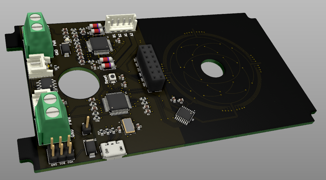
Daisy Stepper Driver is a closed-loop stepper controller that can be daisy-chained.
A stepper controller is a dual h-bridge circuit for controlling a stepper motor. You may be familiar with the A4988 stepper driver common in 2020s 3D printers. This board includes a more advanced model of the same. It can drive any one stepper motor at 24V up to 2A.
Closed-loop means that the board has a brain chip (MCU) that can read the motor position as well as direct. This way it can tell if it missed a step, bumped into something, is being driven, etc.
Daisy-chained means that they can be hooked sequentially. Sequential wires are much shorter. Shorter wires make for easier construction and repair. They are designed for up to 6 Daisies in a row. The Daisies talk to each other via the CANopen protocol.
The MCU is an STM32F103. In speaks CANopen natively while driving the stepper and listening to the sensor.
The CANopen master at the base of the robot can be any MCU that speaks CANopen. It synchronizes each motor and provides a single USB or bluetooth serial connection to the world.
What does this have to do with robots?
This board is designed to fit inside each gearbox of the Sixi 3 robot arm.


The old way a wire from every part had to run all the way through the arm and out the base. To replace the second joint from the bottom you would have to dismantle the entire arm. In the daisy chain model you only need to remove the elbow and disconnect the two cables to the next link in the chain.

Here’s a video of the arm moving IRL. Note the large cable hanging off the side – this version does not have the board in yet. It is the “outside” version of the wiring. I live in constant anxiety that they will get caught on something while moving.
Editor’s note – in this video one motor misbehaves. It was later found that the motor was negative 400-steps per turn instead of the expected 200-steps-per-turn.
Why isn’t the board in already?!
To test the board I have to be able to program it. To program the STM32F103 MCU I need to flash it with a bootloader via the programming pin J6. I have an STLINK V3 MINI to flash the bootloader BUT the MINI has male pins at 1.25mm pitch and my board’s J6 is 2.5mm pitch.


Editor’s note – I believe the larger connector is also a reversible connector.
Do you want to see this board get done? Say something nice on Discord.
What comes next?
Assuming this board is good and can be programmed… the next tasks are:
- mount the board in the actuator
- attach the disc to the output of the gearbox
- run wires from one to the next and test the daisy chain
- get an appropriate brain board and drive everything synchronously
- make more boards
At the last stage it will be time to go to Kickstarter to scale production and bring the price down.
Did you design this board yourself?
No, and I’m proud of it! I have played with KiCAD in the past and done a few but this was beyond my skill. I found a great EE on Fiverr, gave him my specs, and he routed everything in a couple of days. Truly blown away by his skill. He even had a PDF step-by-step guide for ordering from PCBWay so I didn’t have to assemble the board or nothing.

Sadly, he closed his account and I have no way to reach him any more. Electroniikka! If you’re out there, know that I want to work with you again. I love working with talented people, it’s fun, easy, and it helps me scale up to the speed I long for.