Jumbotron LED Display Questions
Shop › Forum › Everything Else › Jumbotron LED Display Questions
- This topic has 23 replies, 2 voices, and was last updated 8 years, 9 months ago by Anonymous.
-
AuthorPosts
-
2017-05-14 at 17:17 #13098AnonymousInactive
Hey,
For my first off-the-breadboard project, I’m building the LED strip display shown in Construct a Giant LED Video Screen. I had a few questions regarding the wiring of the project.
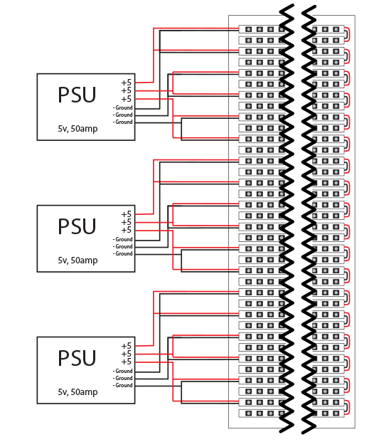
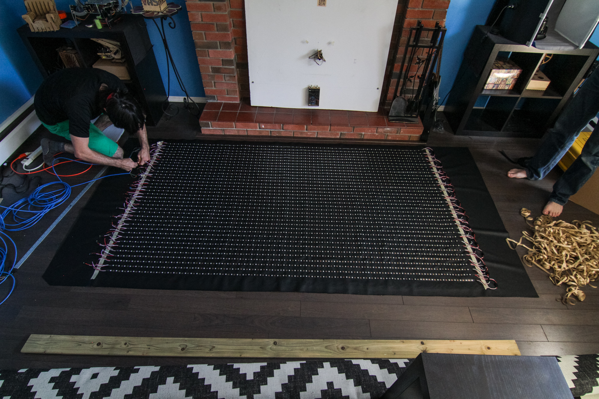
- On the power wiring diagram, the right side of the display shows a simple connection of 1 to 2, 3 to 4, etc. However, in the picture shown here, it looks like there are significantly more connections. Even if I account for data lines, it seems like significantly more. Am I mistaken?
- How are CAT5 cables able to handle the current required? Rough calculations put each strip at 3.6A, with 8 being powered per cable. In other LED display projects I’ve found, power is a major issue even while using thick gauge copper wire, yet the linked project has no problems.
Thanks
2017-05-14 at 21:19 #13099DanKeymasterGreat questions!
They look the same to me. Every odd numbered strip has a strip has a plug to go to a power connector, and the even numbered strips arrived with wires that go to nothing (and were ignored).
There are 8 wires in CAT5. AWG24 is rated 3.5A for “Chassis wiring”, which is for shorter leads. We use one pair of wires for each pair of strips so each half of a pair is carrying ~1.8A, a very safe amount. They weren’t even warm to the touch.
I hope to see video when you get it up and running – especially if you use the processing sketch to play a video off your laptop in real time.
2017-05-15 at 16:19 #13106AnonymousInactiveHey Dan,
Thanks so much for responding. When (or if) I get everything running, I’ll be sure to take video. FYI, A guy on another forum said he used your exact instructions to make an LED strip display and included a couple pictures.
Every odd numbered strip has a strip has a plug to go to a power connector, and the even numbered strips arrived with wires that go to nothing (and were ignored).
Ok, this makes perfect sense. Most strips you buy come with a single male connector attached. The way you have it wired, the zig-zag layout recommended on the OctoWS2811 Library page, on every even strip that male connector will end up looped back on left side (and ignored). On the right side, I’m seeing the proper amount of lines/connections: power+ground, and data. Based on your writeup, I assume that on the right side when the pre-soldered connectors got in your way, you desoldered them and replaced them with T connectors?
AWG24 is rated 3.5A for “Chassis wiring”, which is for shorter leads. We use one pair of wires for each pair of strips so each half of a pair is carrying ~1.8A, a very safe amount. They weren’t even warm to the touch.
I don’t know how I missed this Googling. I still need to go over the math a little bit more for my own understanding, but very interesting.
I’ll be using WS2813 and CAT6 cabling. Can you foresee any issues with that? WS2813 still runs on the WS2811 controller, and adds an extra set of pins (BO/BI) as backup data lines which I would simply ignore. These lines kick in if there’s a single LED failure to route around it, so the whole strip doesn’t go dark. CAT6 is recommended on the OctoWS2811 page.
Thanks
2017-05-15 at 16:36 #13107DanKeymasterI recall that every strip was replaceable without soldering (not permanently affix to each other). There must have been a connector of some kind. Probably 3 pin JST ?
We asked ourselves the amperage-per-wire question when designing the wall, because we worried it would melt the casing and start a fire.
I haven’t worked with them yet. Lately I’ve been using SK6812. Do you have a datasheet for the ws2813? I haven’t found one yet.
2017-05-15 at 19:57 #13108AnonymousInactiveI recall that every strip was replaceable without soldering (not permanently affix to each other). There must have been a connector of some kind. Probably 3 pin JST ?
Again, makes sense.
We asked ourselves the amperage-per-wire question when designing the wall, because we worried it would melt the casing and start a fire.
I believe you did diligence, I meant I want to run it myself for the learning opportunity. I’ll have some time while I wait for things to arrive from overseas…
I haven’t worked with them yet. Lately I’ve been using SK6812. Do you have a datasheet for the ws2813? I haven’t found one yet.
I’ve heard the datasheets provided by overseas sellers can be a little… unreliable. Here’s what I found so far:
- The datasheet everyone seems to be linking to. I’ve seen this linked in forums and included on Aliexpress seller pages. Doesn’t really speak to its veracity, though.
- Quick writeup by a user on the FastLED Google Group
2017-05-21 at 20:44 #13141AnonymousInactiveHey,
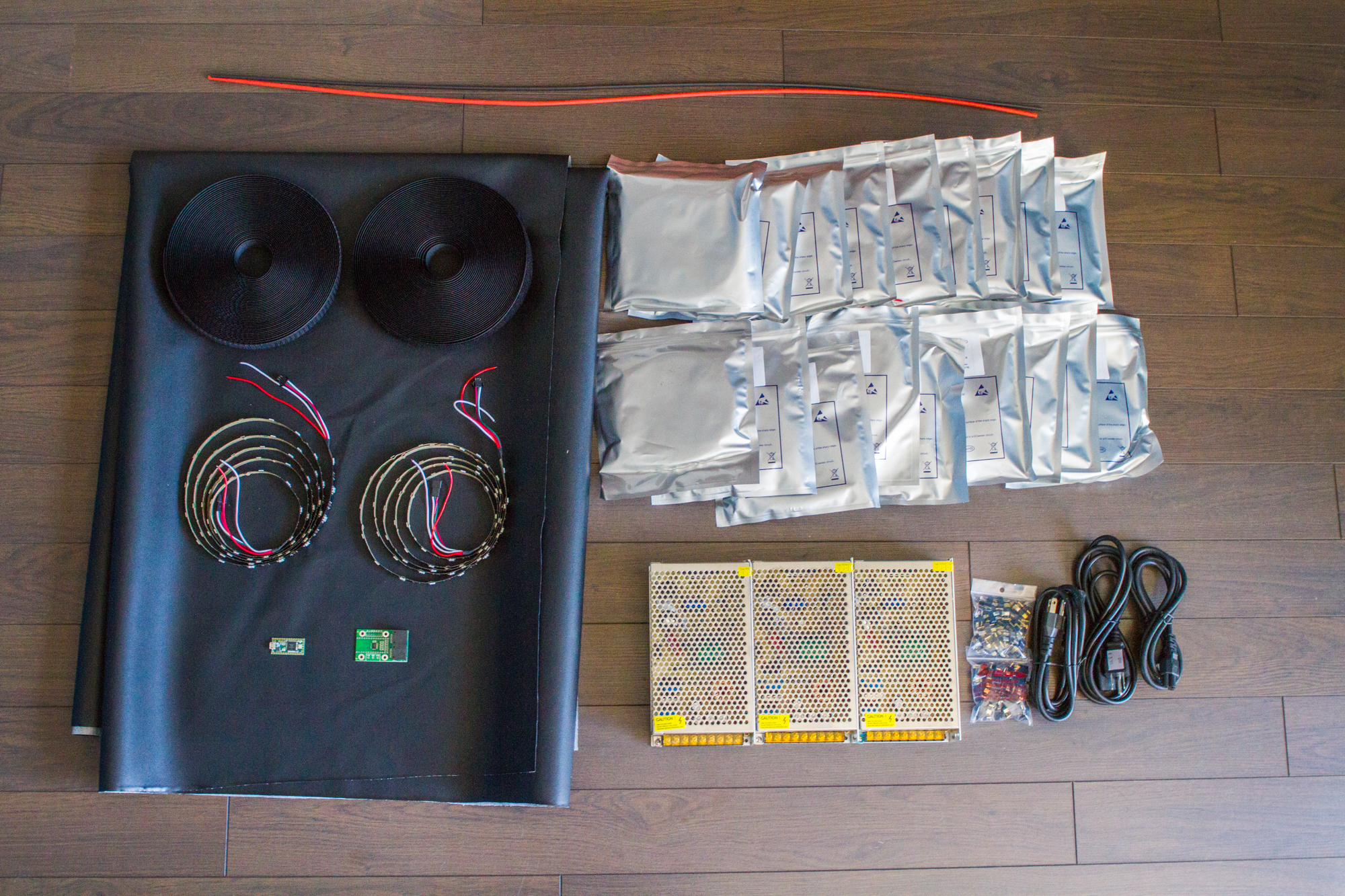
Decided not to complicate things and go with WS2812B’s and a Teensy 3.2, as spec’d in your writeup. As the OctoWS2811 recommends CAT6, and it is the data end, I’ll be using it. If I’m lucky I’ll get CAT6 in 23 AWG.
Going through the build on paper, I had another quick question on the connectors (sorry). Based on this picture and your instructions, the JST connectors are used for data (or skipped if needed) while the red/white wires are connected to T-Connectors for power. Since I can’t find any LED strips with red/white pair included, I assume I simply solder a red wire (matching the CAT wire gauge) on top of the existing JST wire on V+ and white on top of GND? I could desolder, but I’ve heard that even the heat from the solder gun can risk burning out the first LED so I’m avoiding doing it unless recommended or I screw up.
Thanks
2017-05-21 at 21:32 #13142DanKeymasterGood! I like people who keep things simple.
It’s good to be cautious. If you know the wire gauge going into the JST and the power transmitted, maybe you don’t need to solder at all? I don’t really follow your description. Maybe a drawing of what you want to do…
I can say that soldering to the first pins are tricky, we asked the supplier to put the leads on for us and paid a bit extra to avoid the headache.
2017-05-21 at 22:06 #13143AnonymousInactiveSorry for the lack of clarity. Hopefully this hilariously crude image gets the idea across. As always, your input is very much appreciated.
2017-06-22 at 22:25 #13327AnonymousInactiveHey Dan,
I finally got everything constructed and tried to run code tests on it and got weird results. I’ll start by admitting that I’m only using 30 strips as that’s what fits in the frame I’m using, but otherwise I’m using the specs shown on your tutorial.
When I tried to run your version of basicTest.ino, nothing lit up. This didn’t seem to surprising since I haven’t had time to sort out what #define COLS_LEDs, #define ROWS_LEDs 8*3, and the others should be adjusted to. I then tried the default BasicTest that comes preinstalled with Teensyduino within File > Examples > Octo.
I found that if I left the code as-is, the strips plugged in to the data cable lit up. Strips 1-2 and 13-14 lit up fully, while strip 25 only lit about 4-6 fully then faded quickly to nothing after about 10. If I altered BasicTest so that
const int ledsPerStrip = 60instead of the default 120, only strips 1 and 13 lit up, and 25 did the same dim effect.I’m going to run more tests this weekend, but can you think of anything offhand that would explain this behavior?
Thanks
2017-06-23 at 20:36 #13335AnonymousInactiveSome follow-up testing.
I disassembled the entire thing last night, put the strips away, and reassembled them in a pretty random order and the same results occurred when I ran File > Examples > Octo > BasicTest, as well as changing the
ledsPerStrip = 60to 120.Interestingly, I was able to get the default movie2serial.pde (not your branch) to open a video file. It lit up strips 1-4 and 13-16, while strip 25 once again petered out after a few LEDs. Worth noting that the LEDs were bright, but the wrong colors.
On the physical end, I tried running movie2serial.pde, then traded data inputs between strips 1, 13, and 25 and it didn’t change the outcome. Trading the power inputs didn’t change the LED outcome, but yielded an odd result. I noted the CAT6’s providing power to strips 25+ was fairly warm, while the others were not. I swapped the CAT6 for 25+ for the CAT6 powering 1-8. Once again, despite being a different cable, the CAT6 powering 25+ warmed up.
Pretty lost at this point but testing more tomorrow.
2017-06-23 at 21:40 #13336AnonymousInactiveIs there a way to edit posts?
In a bit of paranoia, swapped out strip 25 and it turns out it’s faulty. It was fine in individual testing so it must be a new solder joint. So, when testing with movie2serial.pde, it lights up strips 1-4, 13-16, and 15-28.
I’m testing further for faulty strips to rule that out
2017-06-28 at 08:40 #13358DanKeymasterI think posts are only editable for 10 minutes after posting.
I’m glad you figured it out! Is it working better now?
(I was away camping, it’s good to be home.)
2017-06-28 at 23:57 #13373AnonymousInactiveHey Dan, welcome back.
After more testing I’m more confused than ever. Regarding hardware, I have a migrating failure point that seems entirely resistant to troubleshooting. This time it started at strip #1. The first 10 LEDs or so barely lit up, then the rest of strip #1-12 were dead until the next data input strip, #13. However, after swapping out strip #1 with several others randomly, the issue migrated to strip #14 in a slightly different manner. Strip #14 still lit up at the power+data connection point (far right) but not at full strength; it made it to the end but faintly. All strips after #14 (#15-#24) refused to light up until the next data input strip, #25. The problem persisted after swapping out both strips #13 and #14 with other strips multiple times, swapping the Cat6 power cable for the entire group with another group’s, and swapping the data input cable. Baffled.
On the code end, more weird stuff.
If I used PJRC’s included basicTest.ino, if I left
const int ledsPerStrip = 120only data input strips + the next strip after would light up (#1-2, #13-14, #25-26). To get all of them lit up (except #15-24, which were glitched out as mentioned above), I had to setconst int ledsPerStrip = 720. And it updated quite slowly.If I used your version of basicTest and PlasmaAnimation, on strips with data input, it lit up the first four strips and 16 LEDs on the next strip then abruptly stops (1-4 & 5; 13-14; 25-28 & 29). Note that only 13-14 lit up because as mentioned above, strips #15-24 refused to light up. I have to guess the extra 16 LEDs has to do with the fact that my strips are 60 long while yours were 64 long.
Do you have any idea how I might remedy ANY of these issues?
2017-07-12 at 17:17 #13475AnonymousInactiveHardware issues fixed so all strips light up. The problems with dead strips were due to incorrectly soldered T Connectors: soldering neutral + live to the wrong ends. Oddly, the outcome was different for both. With one strip, it caused the strip above it to light a few LEDs then stop, and all strips after that (including itself) to appear dead. With the other incorrectly soldered strip, it caused itself to light a few LEDs then stop, and all strips after it to appear dead.
Now working through the code issues, which remain identical as described in post above this. Any suggestions on the code would be great.
2017-07-17 at 20:07 #13504DanKeymasterEh… you’ll have to refresh my memory. I tried to scan back through the thread and I don’t find what are your current software challenges.
2017-07-17 at 20:46 #13505AnonymousInactiveHey Dan, of course.
I’m running all code included when I downloaded Teensyduino a couple months ago. Your code is custom for 36 strips with 64 LEDs each and I’m only running 30 strips with 60 LEDs each, so I wanted to make sure I could get the basic stuff up and running. I realize that that’s not your original 36 strip design, nor is it divisible by 8. My understanding from reading PJRC forums is that the only issue is that the imagery will be cut off early, and the code runs/uses memory as if the missing strips were there. I went with 60 leds per strip as that is all I could find.
I’m running WS2812B’s, and I didn’t alter the code anywhere it mentioned WS2811 because my understanding is that it should be compatible, and I didn’t find any PJRC posts recommending code changes.
The issues I’ve encountered are all similar:
- When I run the BasicTest.ino, the only strips that light up are the data input strips, and the strip connected below it (strips 1-2, 13-14, 25-26). If, at the top of the code:
...
#include <OctoWS2811.h>

const int ledsPerStrip = 120;

DMAMEM int displayMemory[ledsPerStrip*6];
int drawingMemory[ledsPerStrip*6];
...
I alter
const int ledsPerStrip = 120toconst int ledsPerStrip = 720all strips light up, but at a complete crawl. It can take a full minute or longer for the colors to switch. - If I run PlasmaAnimation, an almost identical problem. The only strips that run are the data input strips, and the strip connected below it (strips 1-2, 13-14, 25-26). If, at the top of the code:
...
#include <OctoWS2811.h>

//OctoWS2811 Defn. Stuff
#define COLS_LEDs 60  // all of the following params need to be adjusted for screen size
#define ROWS_LEDs 16  // LED_LAYOUT assumed 0 if ROWS_LEDs > 8
#define LEDS_PER_STRIP (COLS_LEDs * (ROWS_LEDs / 8))
...
I alter
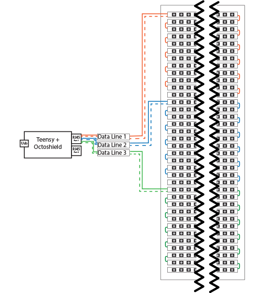
ROWS_LEDs 16to ROWS_LEDs 96` all strips light up, but at a complete crawl. - If I run VideoDisplay.ino + Movie2Serial.pde, a slight change: the strips that run are the data input strips, and three (3) strips connected below it (strips 1-4, 13-16, 25-28).
- And just for reference I did try to run your version of BasicTest.ino. The strips that run are the data input strips + three (3) strips connected below it, and 16 LEDs on the next strip (strips 1-4 and some of 5, 13-16 and some of 17, 25-28 and some of 29). I assume this has to do with the fact that your strips have 64 LEDs and mine have 60.
I have asked PJRC for help and it looks like they’re reviewing it, leaving a quick note saying it looks like a hardware issue. Just in case, I’ve purchased another Cat6 cable to create another data line, as well as another micro-b cable.
2017-07-17 at 20:50 #13506AnonymousInactiveArgh, I forgot links to the code and I can’t edit posts at all:
2017-07-17 at 21:20 #13507DanKeymasterI just opened basic test and all I can say is…. oops? the code there is for the original LED wall at VHS which has a crazy wiring scheme and is nothing like the MAKE wall (much more straightforward).
I have updated all code in the repository for the 64×36 branch. Please update and let me know if that helps.
2017-07-17 at 21:25 #13508AnonymousInactiveAh, that probably explains a lot. I’m still setting up and tearing down each time, so I’ll run your updated branch tomorrow evening and provide and update here. Many thanks.
2017-07-18 at 19:44 #13521AnonymousInactiveHey Dan,
Ran your code. As previously noted:
- I have 30 strips right now due to the size limitations of my holding case. If you think it will help troubleshooting, I’ll solder up an additional 6.
- Each strip has 60 LEDs, not 64, as multiples of 30 was all I could find
On to the testing:
- When I ran your BasicTest.ino, this was the result (photo). The strips that light up are all at data inputs, the three rows below, and 16 LEDs on the next strip (strips 1-4 and some of 5, 13-16 and some of 17, 25-28 and some of 29).
- When I ran your plasmaAnimation.ino, the same strips lit up (photo).
- When I ran your rainbow.ino, the same strips lit up (photo).
- When I ran simpleShapes.ino, the same strips lit up (photo).
- When I ran videoDisplay.ino + screencapture, the same strips lit up (photo). It did seem to react to screen movement, but it wasn’t clear.
- When I ran videoDisplay.ino + movie2serial.pde, the same strips lit up (photo) – however, the Processing Java preview was blank, and no video actually played. It stayed completely static.
I don’t know much about C or C++, so unsurprisingly I couldn’t break down your code. For example, in your basicTest.ino, you list
LEDS_PER_STRIP (8*8*4)which = 256. This is also the number of LEDs lighting up for me at each data input area. I don’t understand why that would be set that way though, as your strips had 64 for a single or 128 for a looped double. This confusion extends to basically all of the#definecode, as the numbers don’t seem to logically add up to your build’s height, width, or LEDs. I even tried assuming “panel” was a unit of measurement for a block of LEDs or strips.2017-07-21 at 08:03 #13540AnonymousInactiveHey Dan,
Is it possible that the OctoWS2811 adapter just isn’t operating? When I tried to run the FastLED Octo example (FastLED/examples/Multiple/OctoWS2811Demo/OctoWS2811Demo.ino), once again only the data input strips lit up. I found that if I altered Line 6
#define NUM_STRIPS 8to any other number nothing changed. Line 5,#define NUM_LEDS_PER_STRIP 60explicitly controlled the exact number of LEDs that would light up at each data input strip.I’d be thrilled to find out, say, I got the wrong sockets + pins combo (picture) or something equally incompetent, as long as it explains it. I’ve posed this question over at PJRC as well.
Other stuff I tried – made a new data cable and acquired a new micro-b cable, then ran testing with them. Same results as listed on July 18. Downloaded the OctoWS2811 library and examples again, and your versions again. Same results.
2017-08-08 at 20:26 #13737AnonymousInactiveHi Dan,
I just ran the updated Github Teensy code and it works! I’m running a 60 wide x 30 tall wall right now, so if I alter BasicTest.ino and PlasmaAnimation.ino so that
#define COLUMNS (64)to(60), it works perfectly. Additionally, you can see VideoDisplay.ino’s placeholder works, albeit cut off on the bottom since I’m working with 30 strips and not 36 (picture).I can’t seem to get movie2serial.pde or screenCapture.pde to work. I’m guessing it’s these lines near 50:
final int SCREEN_WIDTH = 32;
final int SCREEN_HEIGHT = 24;

final int PANEL_WIDTH=8;
final int PANEL_HEIGHT=8;
final int PANELS_PER_PIN = 4;
final int LEDS_PER_STRIP = PANEL_WIDTH * PANEL_HEIGHT * PANELS_PER_PIN;
For the life of me I can’t figure out what a
PANELrepresents. Nor can I understand whySCREEN WIDTH = 32andSCREEN_HEIGHT = 24when your display was 64 x 36. I had someone else much better than me at coding take a look and they couldn’t get a grasp of it either.Also is there a video file size limitation? With movie2serial.pde, I can get the video player to work with a small file (>25mb), but if I try a larger one (215mb) it never loads.
2017-08-08 at 20:34 #13738DanKeymasterThat’s the wierd-ass setup for the wall at the Vancouver Hack Space. it was built as 4×3 separate 8×8 panels, each in a reverse-N pattern. so the first light is (0,0), the next is (0,1), and the ninth light is (1,7).
Make a donation and I’ll make it sane top priority. Help me help you. 🙂
2017-08-08 at 21:21 #13739AnonymousInactiveYEP that’ll do it. Happy to make a donation, check your messages.
-
AuthorPosts
- You must be logged in to reply to this topic.
