How to use a 74hc595 shift register
Using a shift register is a super easy way to expand the number of electronic components connected to an microcontroller like an Arudino or a NodeMCU. We’re going to cover what is a shift register, how shift registers works in theory, how to connect a shift register, and then look at some practical programming examples. Follow along with the helpful diagrams and you’ll have it mastered in no time!
What is a shift register?
A microcontroller gives me the power to change voltage in a circuit using code. An Arduino microcontroller has 13 digital pins that I can control individually. BUT! Sometimes I need more than 13. Instead of buying bigger and bigger microcontrollers I can use a shift registers. One shift register will let me control the voltage on eight pins and only uses three pins on my microcontroller. Where it really starts to get exciting is when I daisy chain the shift registers – two daisy chained shift registers can control 16 pins and still only uses three pins on my microcontroller.
How does a shift register work?

To understand how shift registers are used, it can help to understand what’s going on inside the chip. This is a functional block diagram of the parts inside a shift register package. Each block represents a sub-circuit called a latch. Each of these latches has a power in pin, a set pin, a data pin, and an output pin. When the set pin voltage goes from low to high the latch saves the low/high state of the data pin. The saved state in the latch is always being transmitted on the output pin.
The latches down the left side are chained to each other in series. When the voltage on the SRCLK pin changes from low to high, the latch will store whatever is output by the previous latch and the first latch will store whatever is output on the SER pin. Every time SRCLK goes high the contents of the latches moves over by one latch. If there’s a shift register B attached to this shift register A, B-SER (pin 14 on the DIP 16) can read from A-QH’ (pin 9 on the DIP 16).
So far this solves one challenge (connect many things to a few pins) and introduces a new one: What happens if you only want to change the voltage on, say, pin 5? If you try to shift in 8 new values, each SRCLK high/low might change the output of latch 5 in ways you don’t want. There needs to be a buffer, a way to say “I’ve shifted in all my new data (with only pin 5 changed), now change the voltage once on all the pins coming out of the shift register.”
The latches on the right hand side have their data pins connected to the latches on the left. The latches on the right have all their set pins connected to RCLK. When RCLK goes from low to high the output of all eight of the latches on the left are copied into the latches on the right and the output pins change once. Nice! Problem solved.
Lastly, there are two more features that make this shift register extra excellent: First, while the OE pin voltage is high it will turn off all the outputs from the eight shift register pins without losing any saved states in any latch. Second, when the SRCLR pin goes high it will wipe the memory of the left-side latches without affecting the right-side latches. Depending on what you’re doing they can be very useful.
So now that we understand the theory of how these work, let’s get down to wiring and then some practical example.
Wiring a shift register to an Arduino
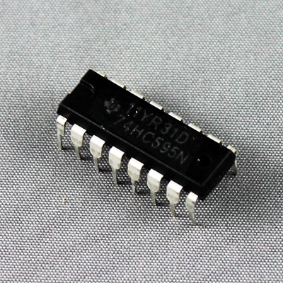
I’m going to connect an Arduino to a shift register to eight Light Emitting Diodes. The LEDs are to show the changing voltage on each output pin of the 74hc595n shift register. I googled for a shift register data sheet and used the pins out instructions to connect a shift register to an Arduino with a breadboard and some wires. Here’s the the shift register, a standard DIP 16 package:

That the bump on the end of the DIP 16 tells you which pin is which.
 Notice the numbers and names on this picture match those in the functional block diagram seen in another part of the data sheet.
Here is a schematic diagram of a shift register connected to an Arduino that I made in KiCAD.

On the left are the pins from the Arduino. In the middle is the shift register. On the right are eight LEDs and eight 220 ohm resistors.
I don’t know why the pins on the shift register are out of order. KiCAD has an eccentric idea of “easy”. An LED without a resistor is a dead LED.
Here’s a picture of the same circuit I built on a breadboard:
Please let me know if you are struggling to make a circuit with this information. I’m here to help.
All together now!
Circuit is built and now I’m ready to test. I’ve put all my shift register code on github for you so you can follow along. There is a single file called one-shift-register.ino that you can load into Arduino software. I assume you’ve used Arduino before and can work your way through code. The main loop() has all our favorite examples.
lightFirst() – light just the first LED.
lightAll() – light all the LEDs.
blinkA() – blink all the lights at once.
blinkB() – same effect, done a different way.
blinkC() – same same but different.
oneAtATime() – light the first, then the second, and so on.
pingPong() – the lit LED appears to move backward and forward.
pingPongSine() – the ping pong effect has a sine curve, so it moves fast in the middle and slow on the ends.
bouncingLevelA() – lighting some of the lights from one end light the levels on a sound board.
bouncingLevelB() – same again, from the other direction.
marqueeA() – the moving lights around the edge of a Broadway show marquee.
marqueeB() – same, different style.
To keep things clear, I give every little job a human-friendly method name.
turnOutputsOn() – turn on the output pins of the shift register
turnOutputsOff() – guess!
clearShiftRegisters() – wipe the stored value in the left-side registers (you didn’t skip “How does a shift register work”, right?)
shiftDataIn(int data) – set the SER pin, then flip the SRCLK pin to high and back to low. all the left-side latches move over by one and the data is now in the first latch.
copyShiftToStorage() – copy the left side latches to the right side latches.
BAM! So good.
Video
Final thoughts
Yes, in this demo I am using five wires. In many applications you can skip the OE and SRCLR wires. Some people even wire the two CLK pins together so they only need two wires.
Yes, the pins coming out of a shift register could control another shift register in some kind of tree-of-registers. In find it easier to daisy chain them. You do you.
Yes, there are many other kinds of shift registers. This is my favorite.
There are many more kinds of latches than discussed here. When you know how latches work, you can start to understand how computers, y’know… compute.
I’ve designed a circuit board that you can solder together so that you won’t have loose wires all over the place. Would you like one?

Comment below and we’ll make it happen. KiCAD did not include the LEDs or the resistors in the 3d preview. I think you can tell where they go. They would be included in the package.
See Also
[products skus=’ELEC-0004, ELEC-0116, ELEC-0067, ELEC-0088, ELEC-0089, ELEC-0090′]
