News Robot Arm
Robot Arm Study 5 in Robot Overlord, Tool mounting design

I’ve got Study 5 working in Robot Overlord. The STL files are heavy in detail so the load time is long, but it works. Forward and Inverse kinematics as good as any other arm in the system (which already includes the 7bot, MANTIS, and others). I still don’t have enough time to rip apart the inner workings and rebuild it with a record & play back mechanism. That would be very nice…

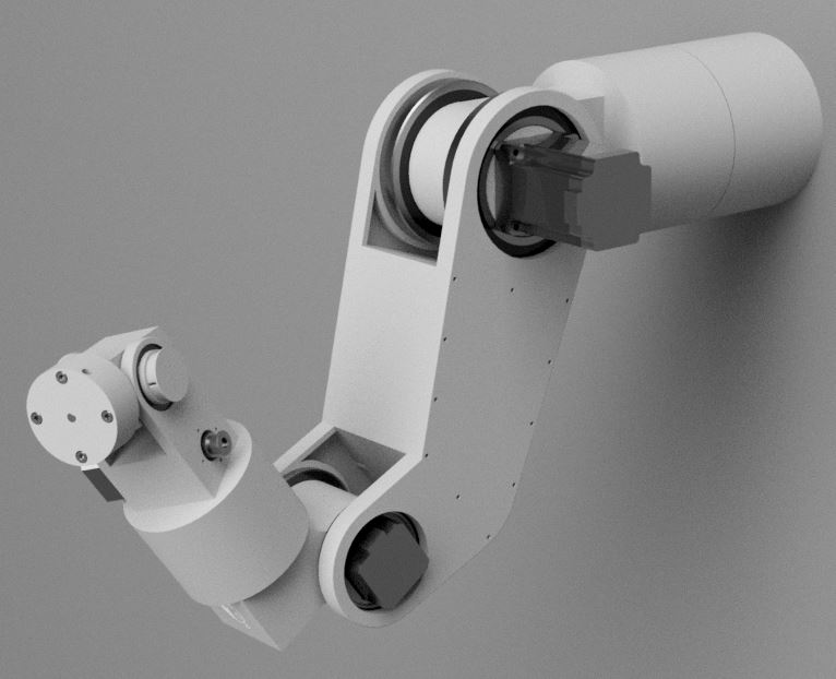
Also here is the hole pattern if you want to design a tool that fits on the wrist of the robot. I would love to see someone design an Automatic Tool Changer (ATC) so the robot could put down one tool, pick up another, and use any tool it is currently holding.