Uncategorized

Building a Delta Robot: alternate design?

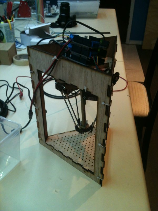
Sometimes I have to think outside the box.  I designed this to be a kid’s game at the Vancouver Mini Maker Faire.  Three people will have to move the red pieces in a team effort to move the blue piece to accomplish some goal (draw a picture, stack blocks, etc).  Notice that this version has a complete frame that rests on a table, while the earlier versions don’t.

It would be straightforward to add three motors that turn screws to move the red pieces up and down.  In fact, here’s a video of a Festo iFab 3D printer that does exactly that.

Tonight I will try printing parts again.  Wish me luck!

Uncategorized

Building a Delta Robot: 3D model version 2

Let’s review: So far…

…I’ve defined success

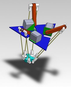
…I’ve used Math ™ to calculate the size of the humerus (red), ulna (yellow), wrist (light blue) and base (dark blue).

…I’ve changed the joints (white) so that they more closely mimic the math (see image).  In the previous version the lengths of the ulnas was much harder to keep track of.  Curious note: I’m told that Solidworks reported a lot of “rebuild errors” with the previous type of joint and those are now fixed.  Yay?

…I’ve written an open source computer simulation of the math, and included Arduino code to run a delta robot with three hobby servos.

…I’ve tried to print the previous joints and found the hole for each bearing was too small.

I have yet to…

…3D print both halves of a joint and assemble a working model.  This is my current challenge.

…3D print the wrist.  Nothing is stopping me, so this will be my next challenge.

…3D print the brackets to hold the steppers (green).  I want to find a way to add a limit switch so that I can calibrate the robot the instant it turns on.  Even better would be a rotary encoder so I could track the arm movement in real time.  I suspect such additions will change the shape of the brackets.

…make the base plate.

…test all the wiring.  Make sure that the steppers move as instructed and that the encoders/switches work.

…make the humerus bars and assemble the machine.

…test axies: moving to zero, then 1 cm on each axis (to make sure +x,+y, and +z are not flipped in my software)

…test range of motion: moving from 0,0,0 to the eight corners of a box at each corner of the envelope.

…test repeatability: moving from 0,0,0 to some fixed point with a digital touch probe.  Repeat 500 times and find the max of the error.

…test drawing straight lines in the air: video the tool moving in front of a checkered background.

… test drawing arcs in the air: video the tool moving in front of a checkered background.

… test speeds: ? ? ? At this point my knowledge completely runs out.

More news Tuesday night when I try to reprint these joints.

Uncategorized

Building a Delta Robot: Kinematics Calculations

Delta Robot v7


Live demo here

Designing a robot is time consuming and investing in parts is expensive. Hardware starts with hard, right? I needed a tool to help me design my delta robots. I wanted something that would let me play with the numbers and instantly see how it would affect the size, accuracy, and power of my machines. Since nothing like it existed, I wrote a Javascript program to do it.

Tweak your robot dimensions and see how it will affect your work envelope and your precision.  Then adjust your motors and check that the forward and inverse kinematics match.

Edit 2014-02: Added more detailed explanations so it’s a bit easier to use.

Miscellaneous

Building a Delta Robot: 3D model version 1


Now that I’ve defined what success should look like, I have to start putting the pieces together.  This started as a set of pen & paper drawings in my sketchbook.  Then I had a friend model the entire thing in Solidworks.  This model uses

  • Some sheet metal or wood for top & bottom plates (blue)
  • Some 3D printed brackets (green)
  • 24 3D printed ABS bearing mounts
  • 12 3/8″ OD bearings (between the bearing mounts)
  • Three pieces of 16mm hollow square aluminum bar (grey)
  • Three NEMA17 stepper motors
  • Six pieces of 4mm threaded rod
  • Six 1cm rods (attaches bearing mounts to square bar & bottom plate)

Before I could say this design is finished I still need to do a number of changes and tests, based on my previously stated goals:

  • The 1cm rods should be supported on bearings to make movement nice and smooth.
  • Bearings means a redesign of the square rod, the 1cm bar, and the bottom plate.
  • The legs that will hold up the delta robot haven’t been designed yet
  • Length of the 16mm square bar, length the 4mm threaded rod, and size of the plates will change once I calculate the correct numbers for the work area and accuracy that I want.  I just hope the motors I have will be up to the task!
  • Solidworks can simulate material stress and do other kinds of performance analysis.  I should be able to test how much weight the machine can carry before I start making anything, which will help me make sure my targets are being met.
Art

Kinect based art project

An 8 foot pole, atop which are 9 Kinect bars facing outward. Their cameras cover 360 degrees around the pole, and together they create a color 3d map of the entire surroundings. The user wears 3D goggles like Occulus Rift and can see themselves in the third person, look behind themselves without turning, peek around corners, and more. Imagine combining it with a UAV or a live satellite feed!

I could probably come up with a lot of BS about human interaction, the nature of technology in society, man’s relation to himself when reduced to an avatar, etc… but the truth is I think it’s just a really neat idea.