Sixi 2 robot arm
7. Pre-Anchor Assembly
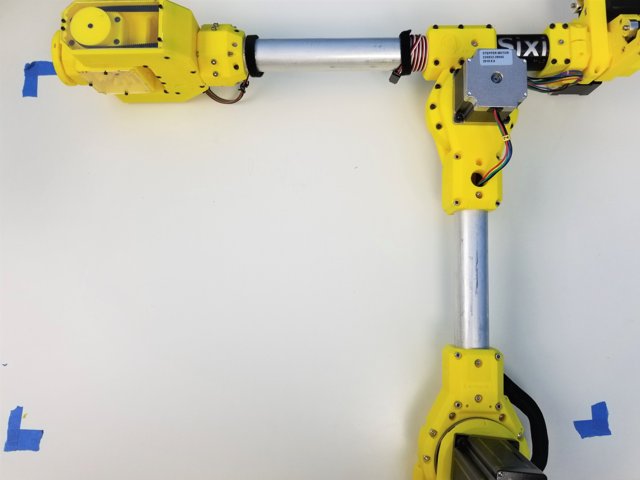
Step 1 Tools and Parts Required for this Chapter
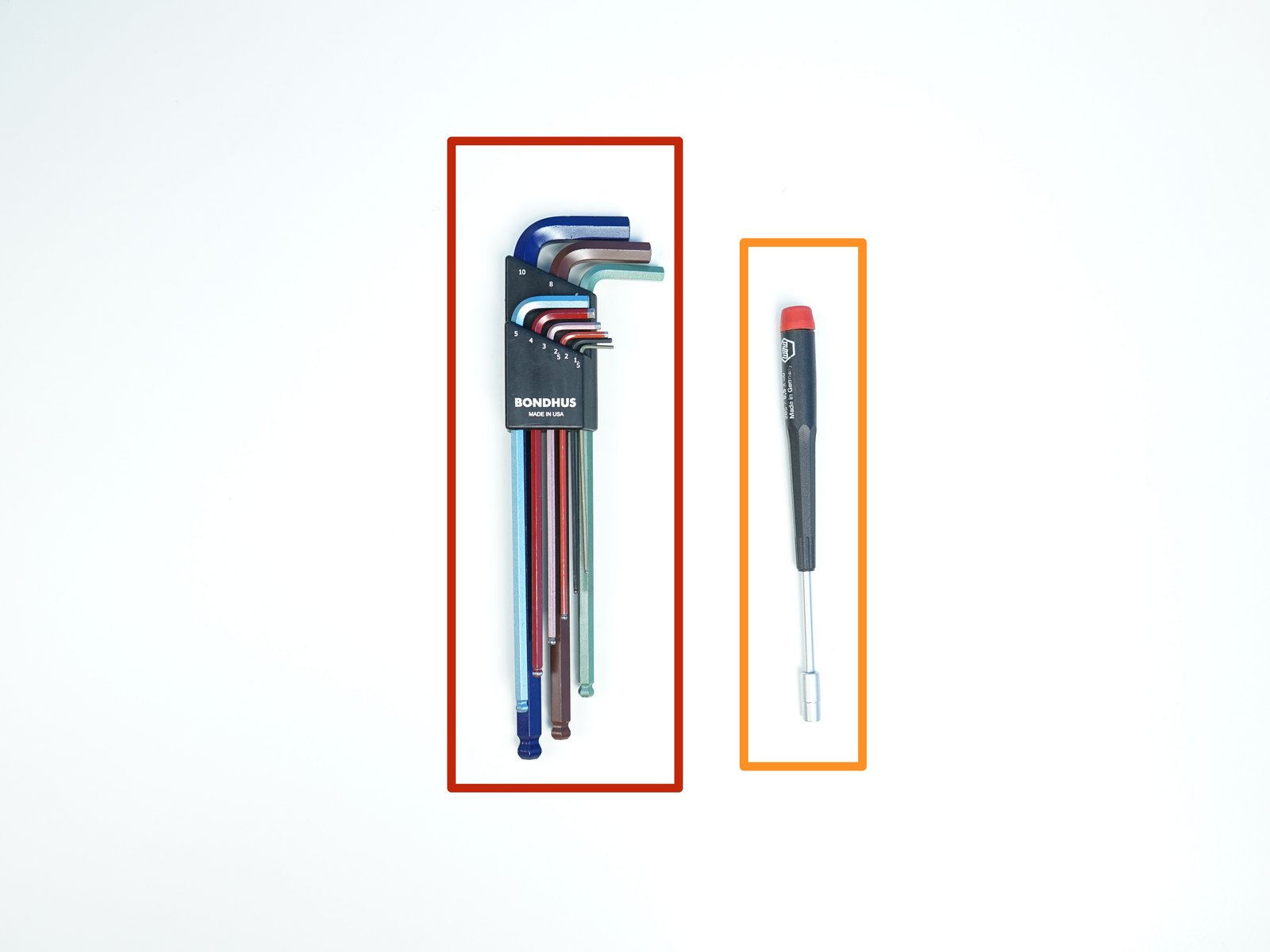
Click the large image to open full size.
Assembled 4,5 & 6 Axis {a.k.a Forearm}
Assembled Elbow Gearbox
Assembled Shoulder Gearbox
Cable Management parts
Alan Keys
Socket Head Driver
Step 2 Elbow to Forearm - Parts
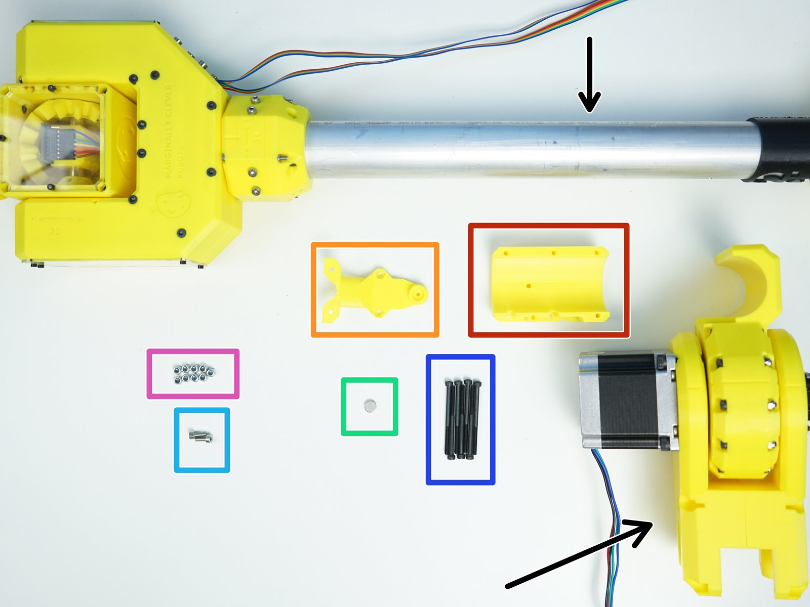
Click the large image to open full size.
- Note:
Prepare the following components:
Assembled Forearm & Elbow Gearbox
[3D] - 3GB Elbow GB Top Cap
[3D] - 3GB Elbow Magnet Holder Bottom
8x2.5mm Neodymium Magnet
M3x8mm Screws (x2)
M3x45mm Screws (x7)
M3 Nylock Nuts (x9)
Step 3 Elbow to Forearm - Elbow Clamp
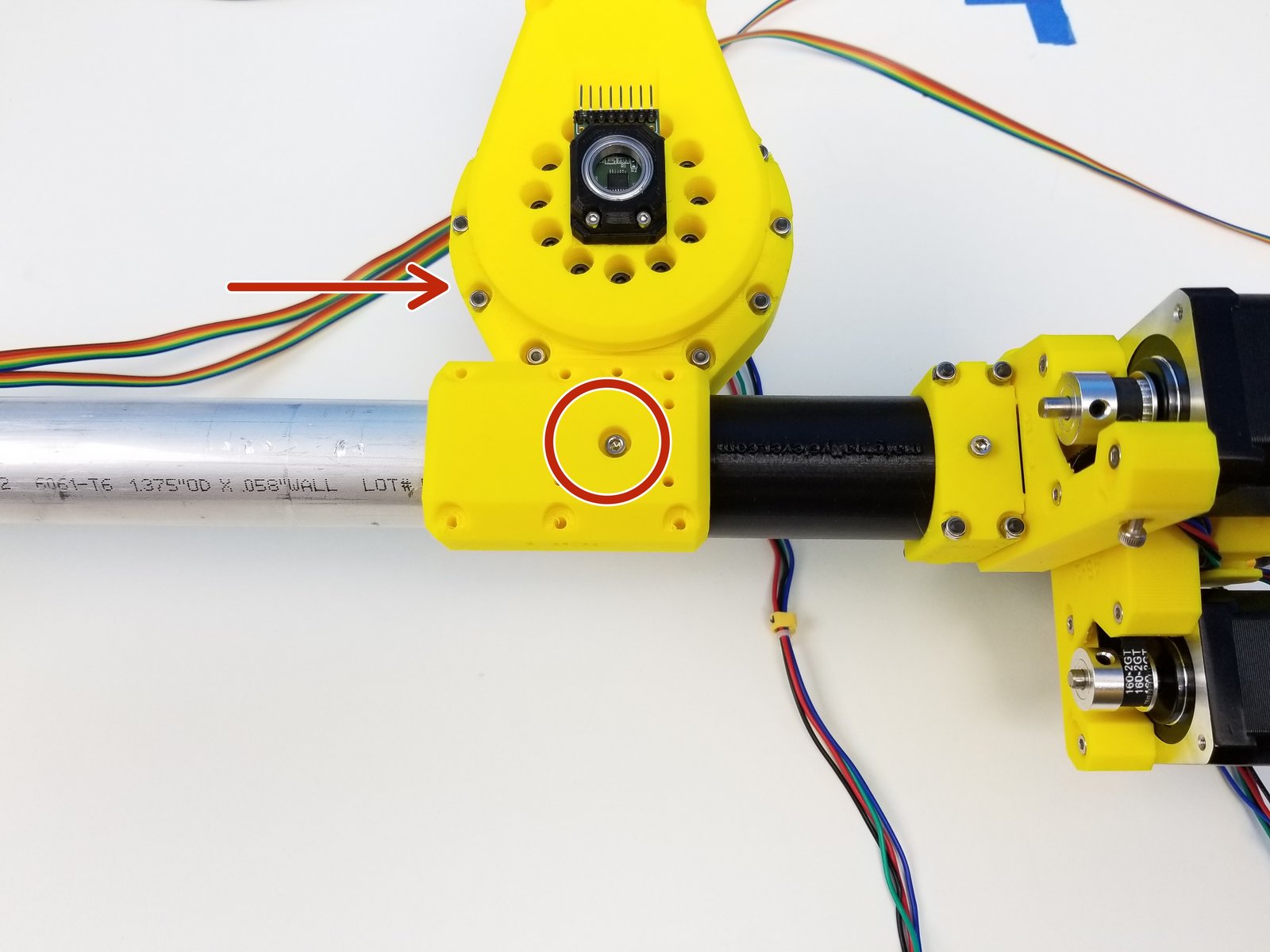
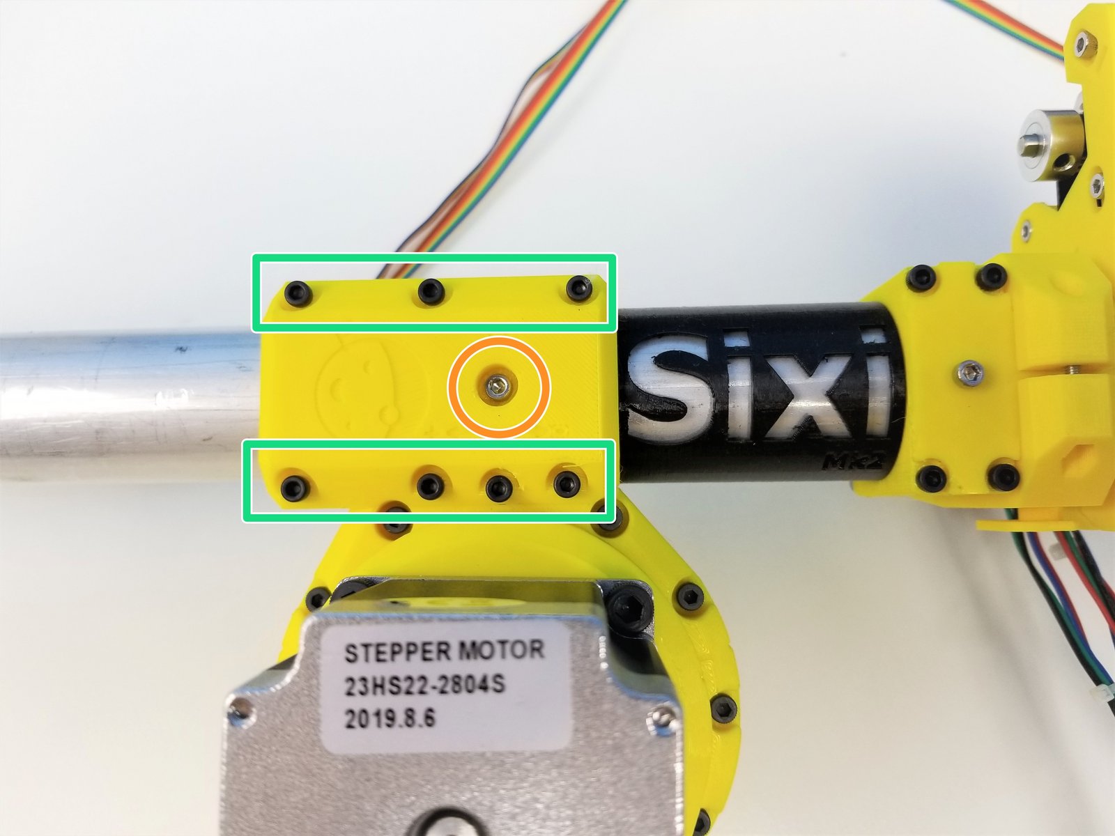
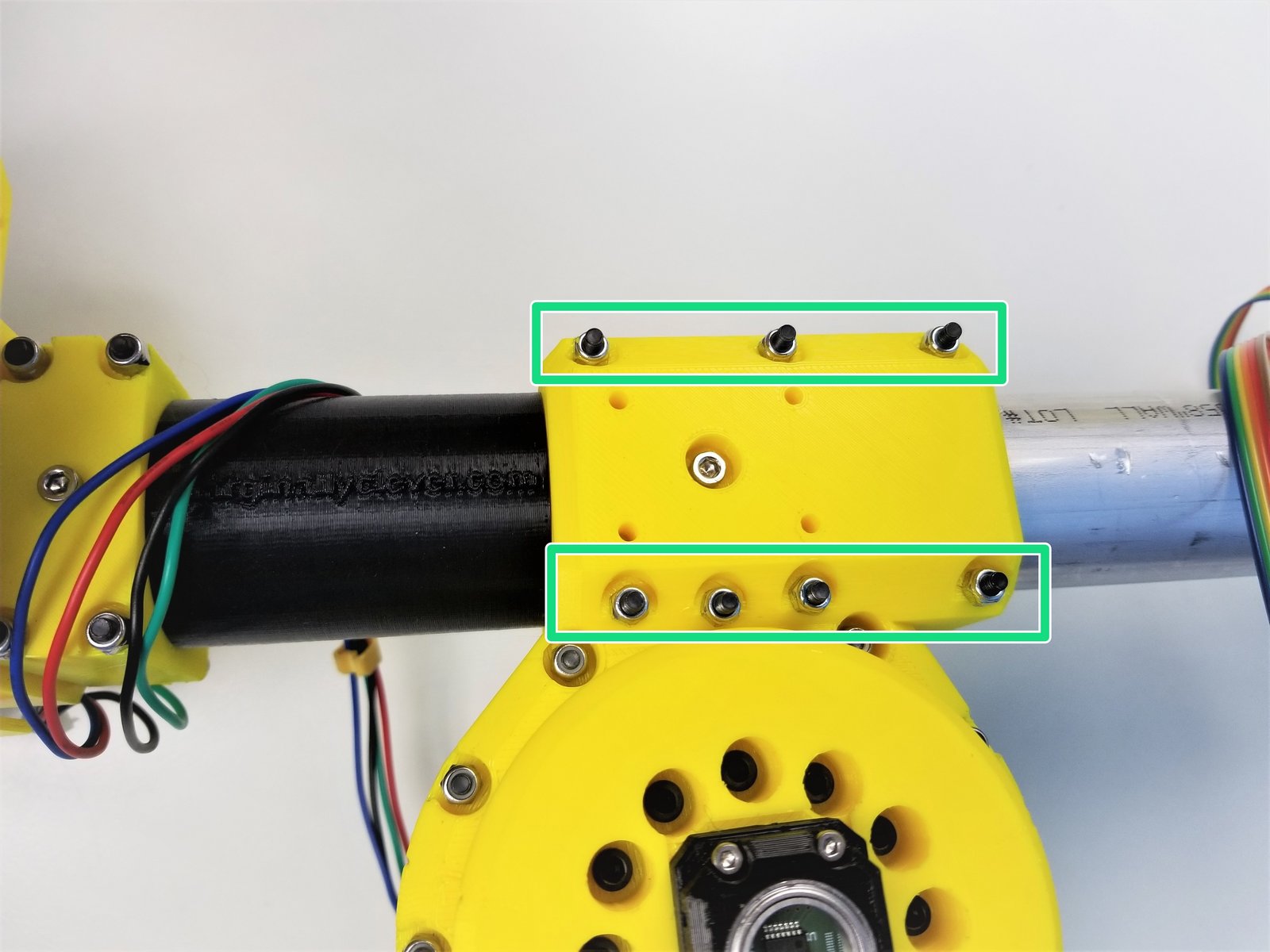
Click the large image to open full size.
Loosely secure the Elbow Gearbox {half} to Forearm using M3x8mm Screw
Repeat the same for the Elbow Gearbox Clamp on the other side using M3x8mm Screw
Tightly secure both Elbow Gearbox pieces using M3x45mm Screws and M3 Nylock Nuts
Step 4 Elbow to Forearm - Elbow Magnet Holder
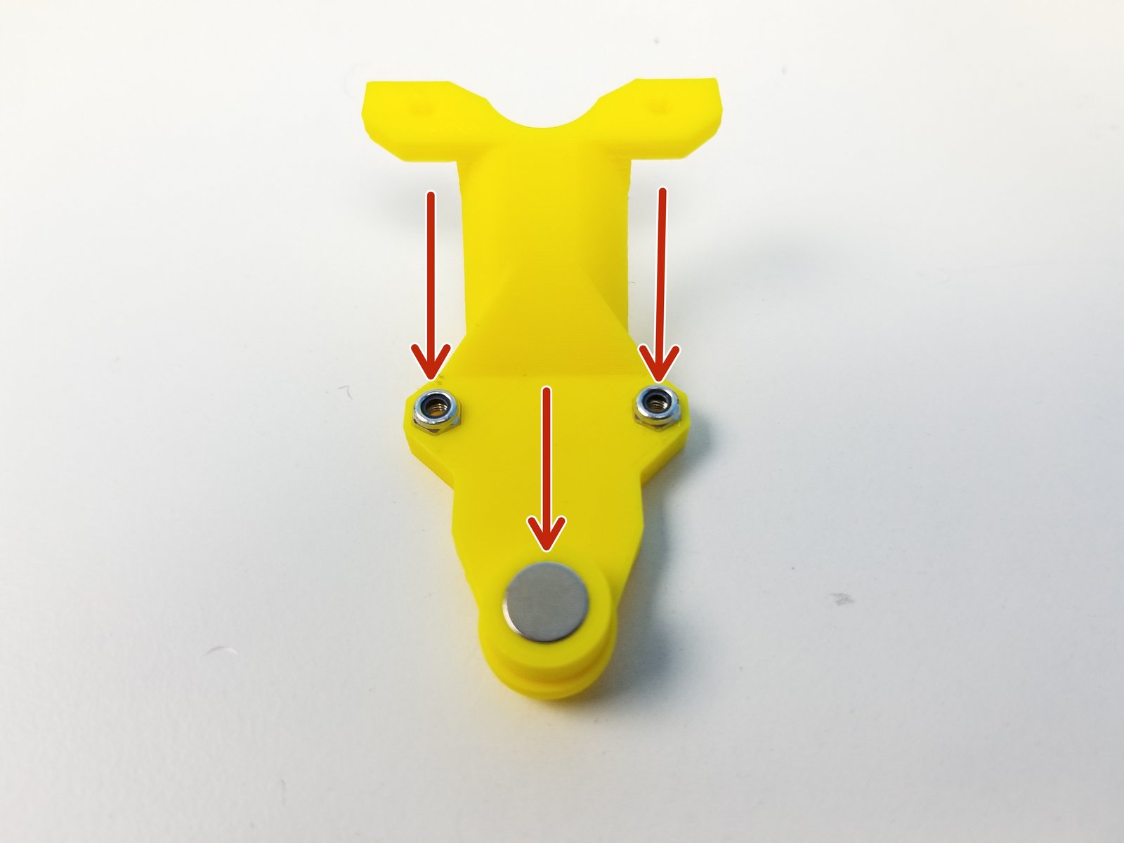
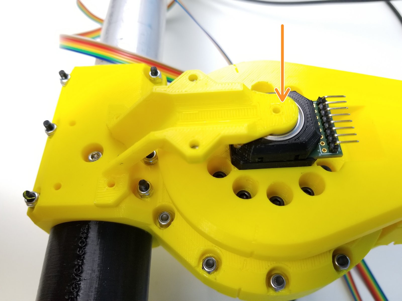
Click the large image to open full size.
Insert M3 Nylock Nuts and Neodymium Magnet into the Elbow Magnet Holder Bottom
Insert the Elbow Magnet Holder to the 6701 Bearing on the Elbow Sensor Adapter
Step 5 Forearm Cable Management - Parts
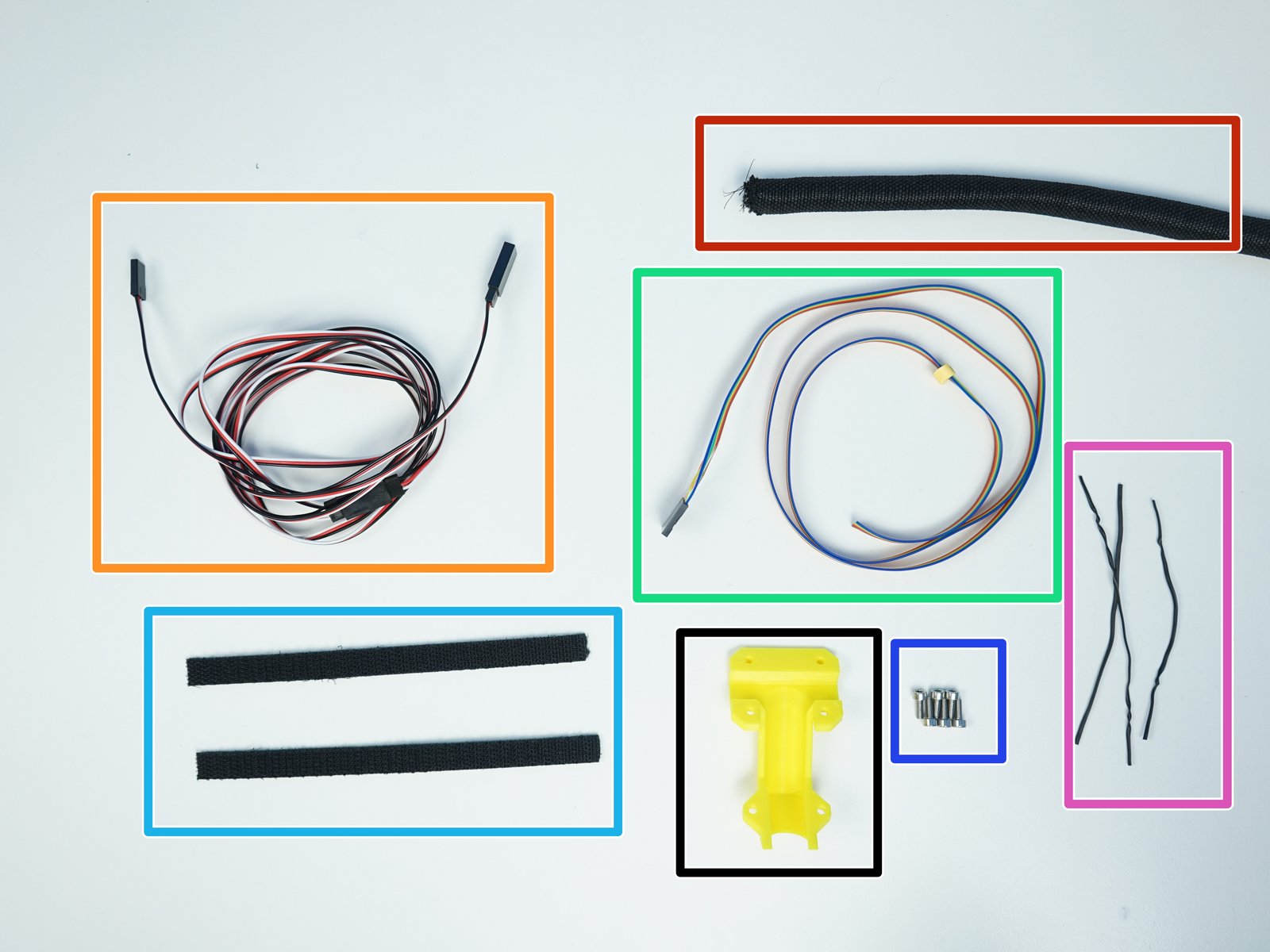
Click the large image to open full size.
- Note:
Prepare the following additional components:
[3D] - 3GB Elbow Magnet Holder Top
Braided Cable Sleeve [950mm]
3-pin Servo Extension Cable M/F - [1000mm] (x2) {already connected to each other}
6-pin Ribbon Cable F/O - Brown to Blue {sensor 2 Elbow} - [890mm]
Velcro Wrap [150mm] (x2)
M3x8mm Screws (x6)
[Opt.] - Twist Tie [100mm] (x3)
Step 6 Forearm Cable Management - 1
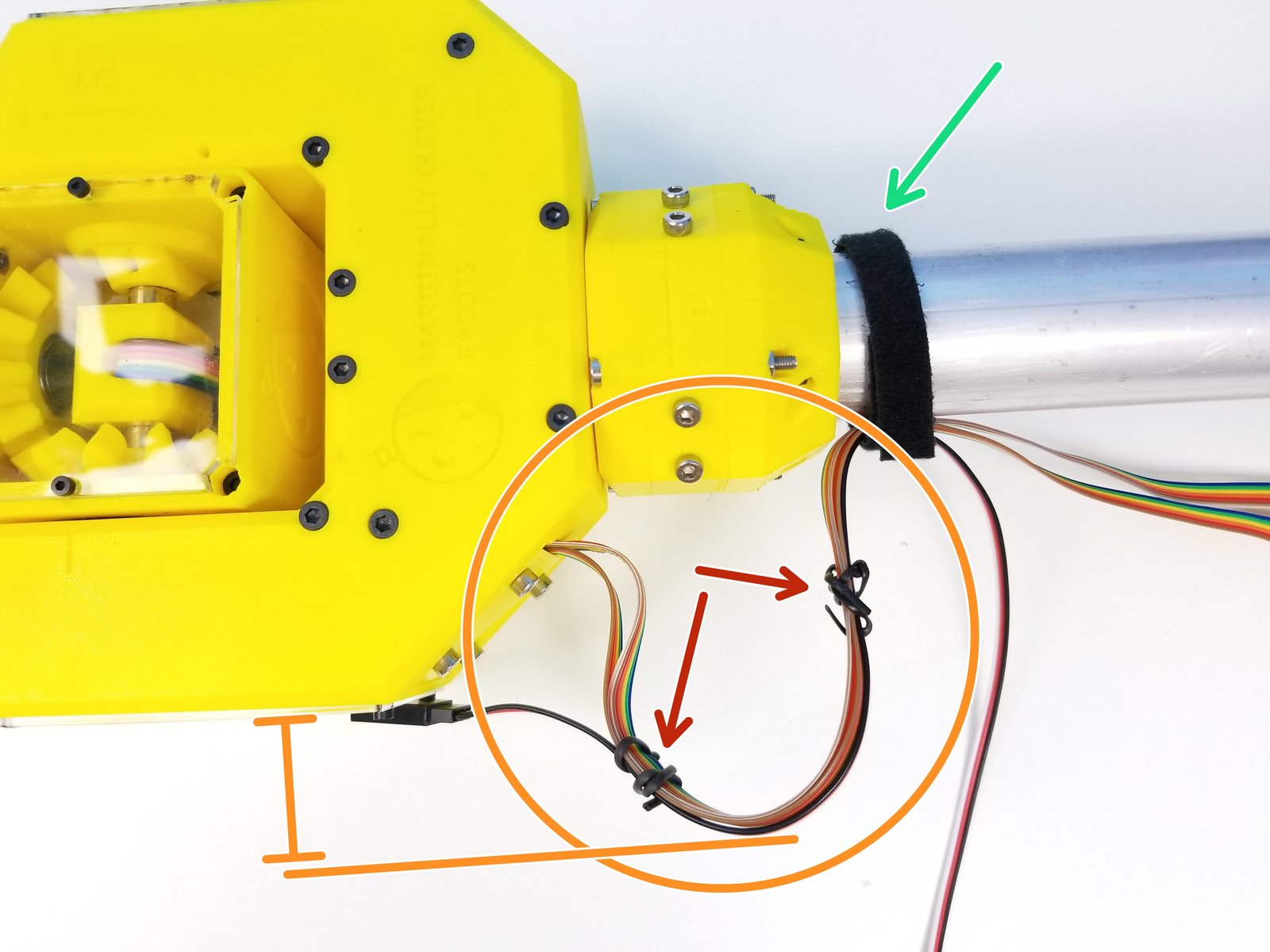
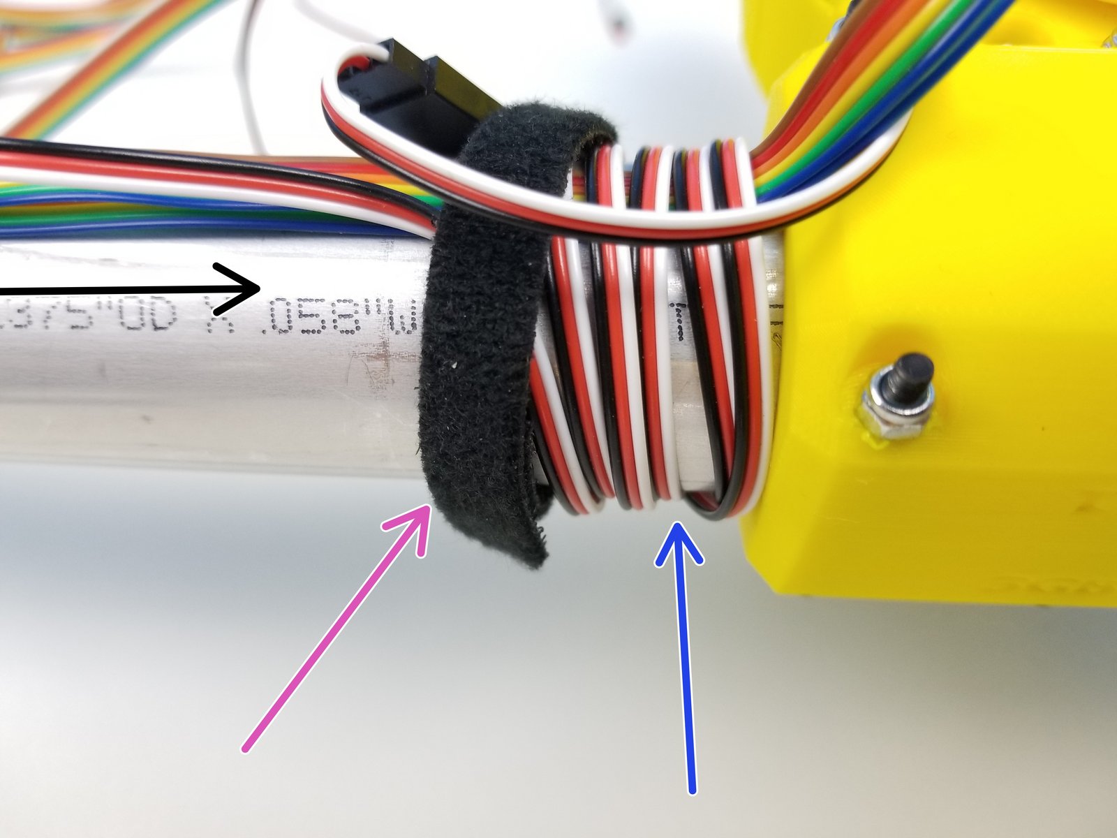
Click the large image to open full size.
Secure the Servo Extension Cable to the Wrist & Hand Sensor Cables using the Twist Ties
Make a curve with the cables so that the ++peak of the curve is about thumb length away from the Fork face
Maintain this curve/bend using the first Velcro
Run the cables along the Forearm Link tightly all the way to the Elbow
Loop Servo Extension Cables 5 times around the Forearm by Elbow Clamp
Secure this loop using the other Velcro
Step 7 Forearm Cable Management - 2
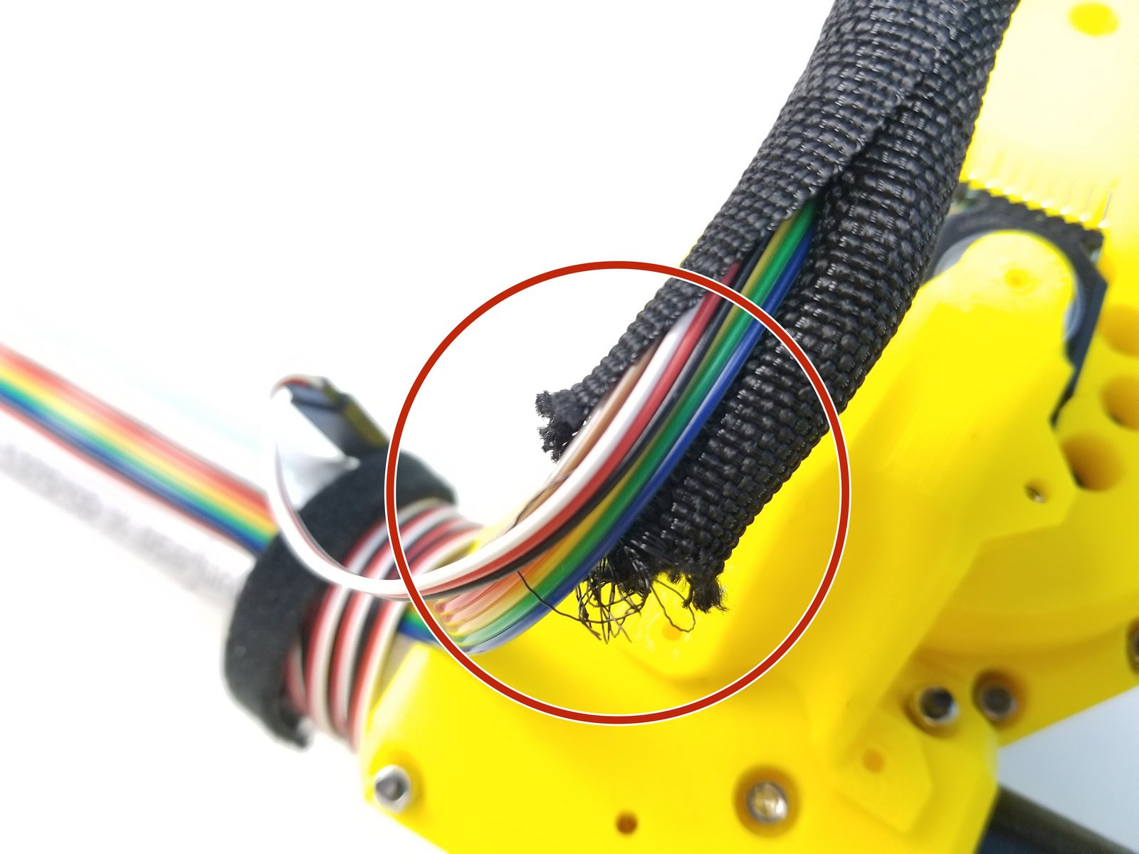
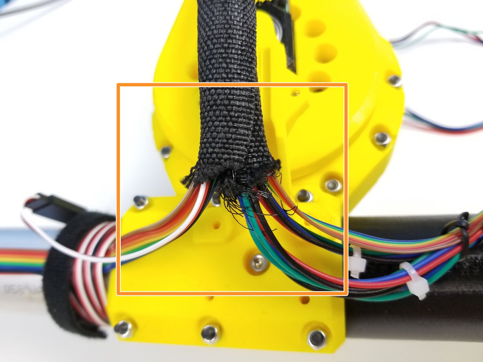
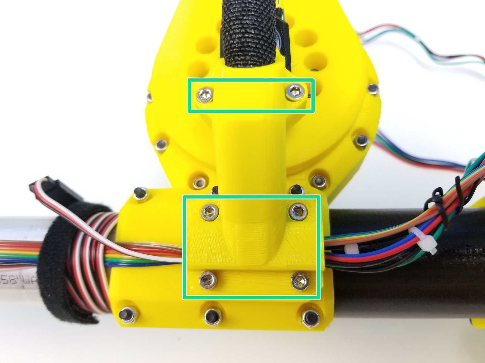
Click the large image to open full size.
Insert all the Cables on the Forearm to the Braided Cable Sleeve at the top of the Elbow Sensor Holder
Insert all the Elbow Tail Motor Cables and Ulna Sensor Cables to the Braided Cable Sleeve as well.
Hide the messy part of the Cable Sleeve with Elbow Magnet Holder Top using M3x8mm Screws
Step 8 Forearm Cable Management - 3
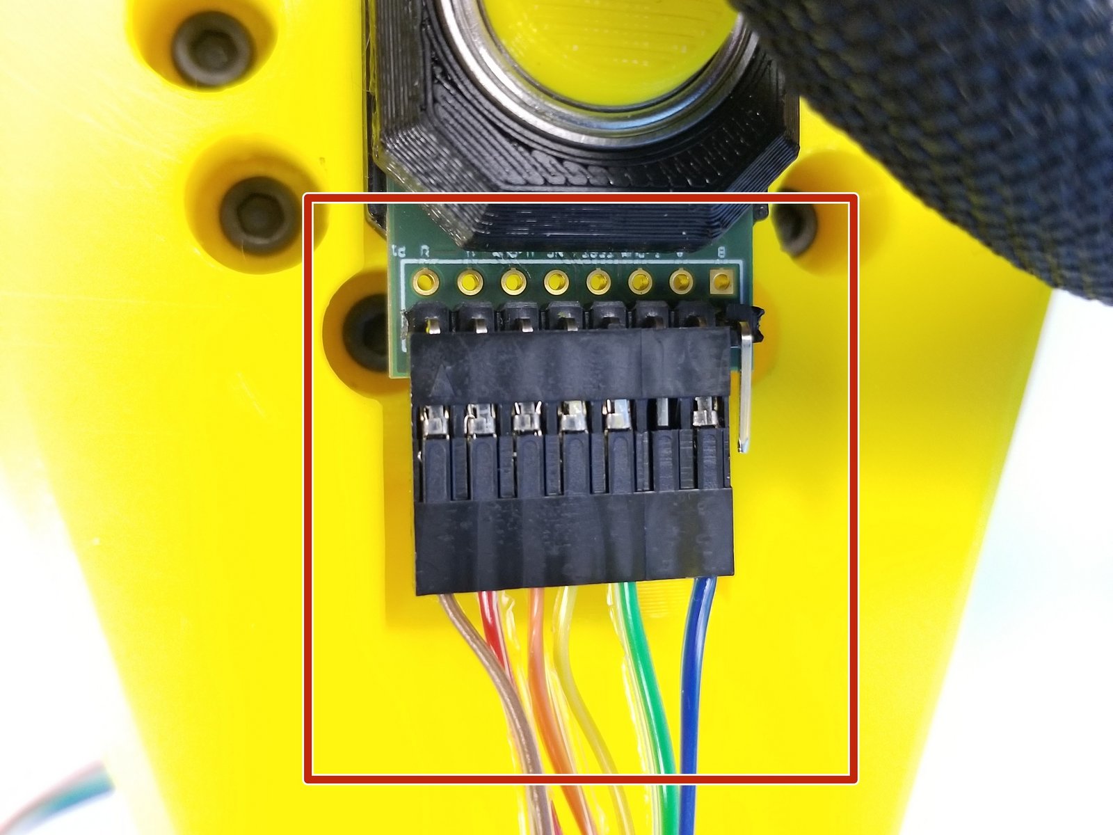
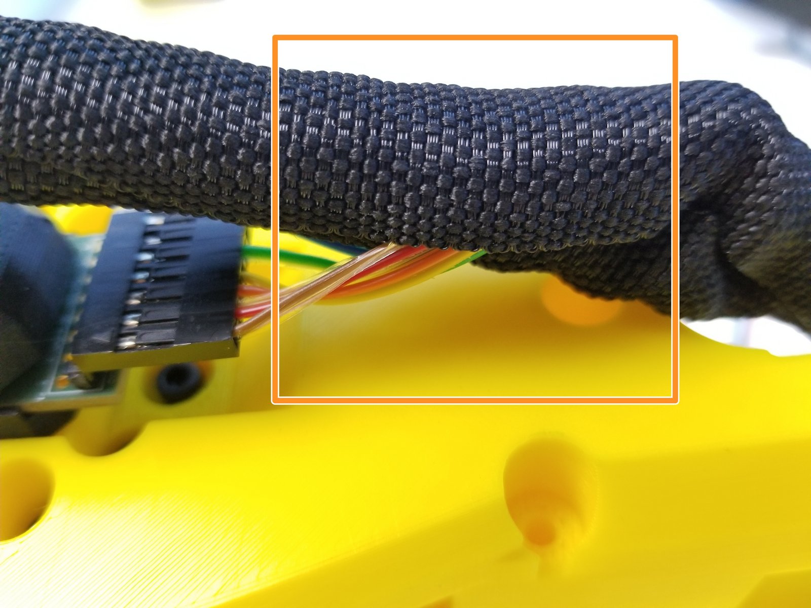
Click the large image to open full size.
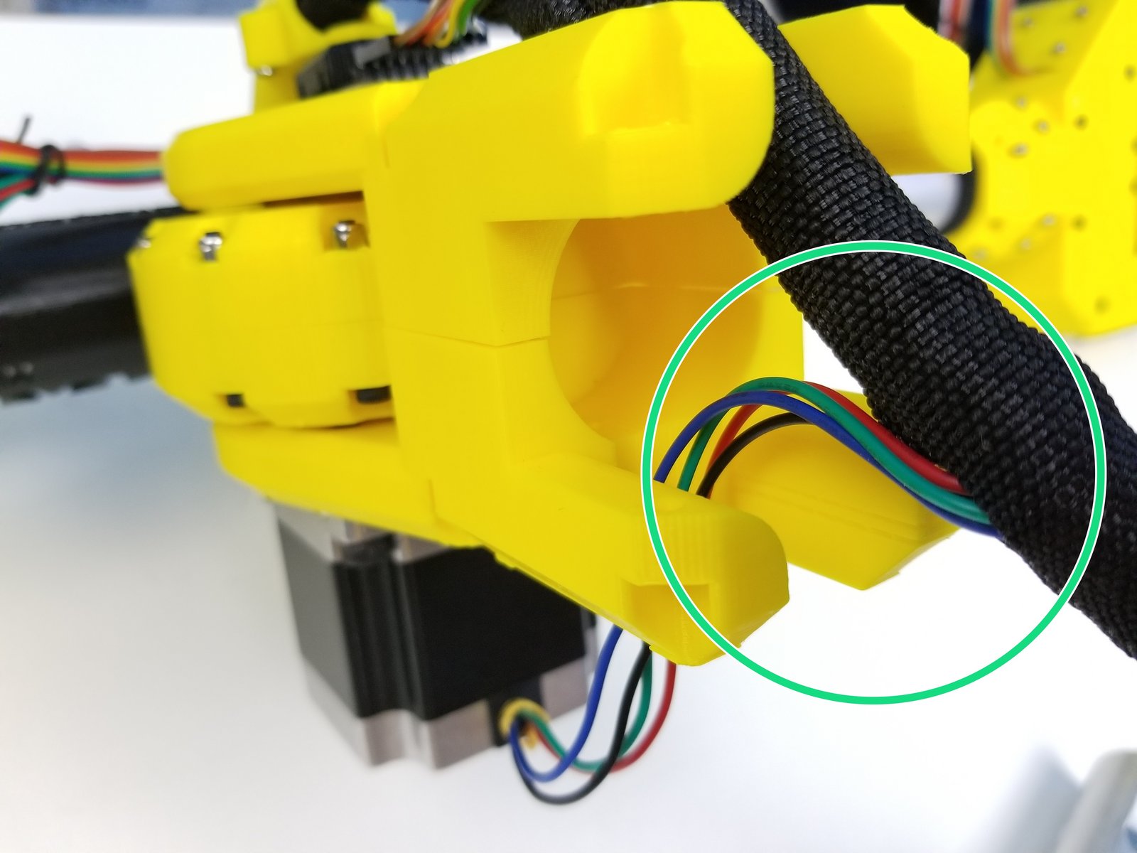
Connect Elbow Sensor Cable to the Sensor as shown in the picture
Insert the Elbow Sensor Cable in the Braided Cable Sleeve
Insert the Elbow Motor Cable into the Braided Cable Sleeve as well
Step 9 Bicep Linkage - Parts
Click the large image to open full size.
- Note:
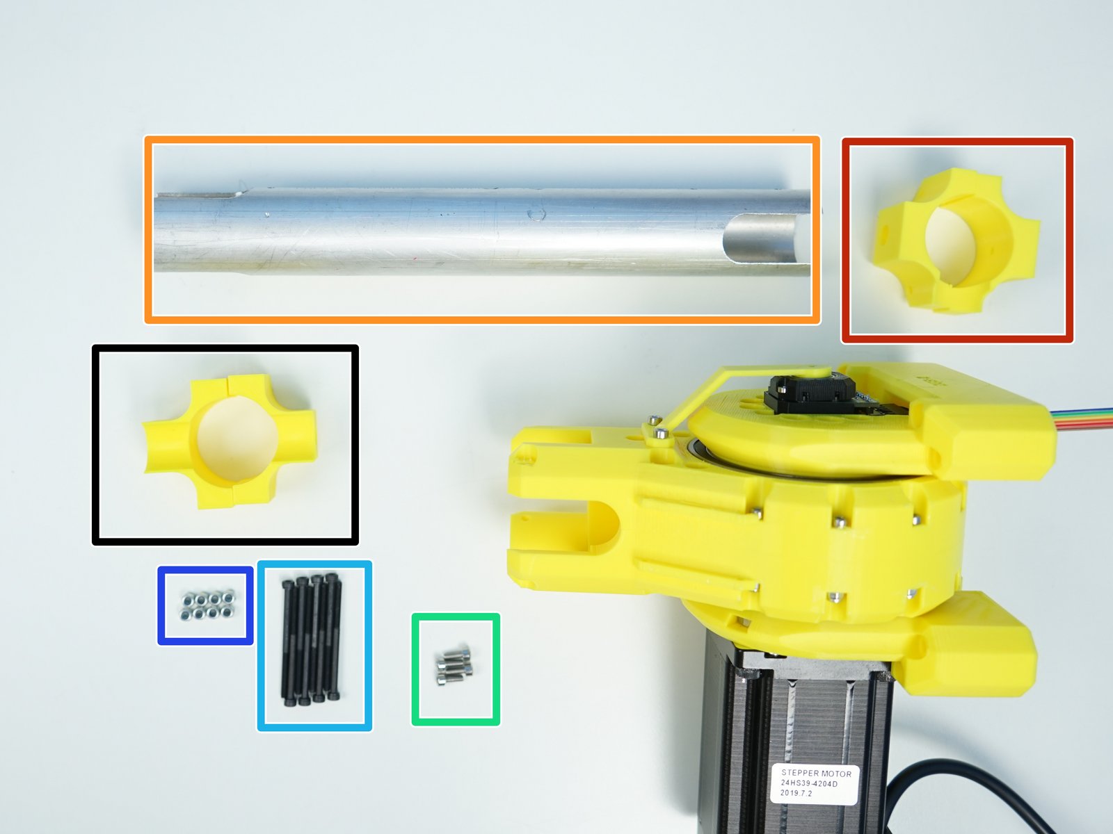
Prepare the following components:
[3D] - 3GB Elbow GB Bottom Caps
[3D] - 2GB Shoulder GB Top Caps
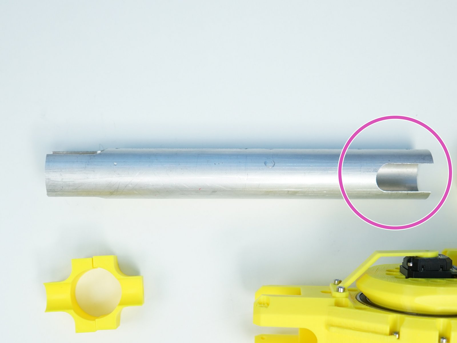
Aluminium Pipe [1.375'x260.25mm]
M3x8mm Screws (x4)
M3x45mm Screws (x8)
M3 Nylock Nuts (x8)
Single U-Cut end is the Shoulder Gearbox End
Step 10 Bicep Linkage - Elbow Gearbox
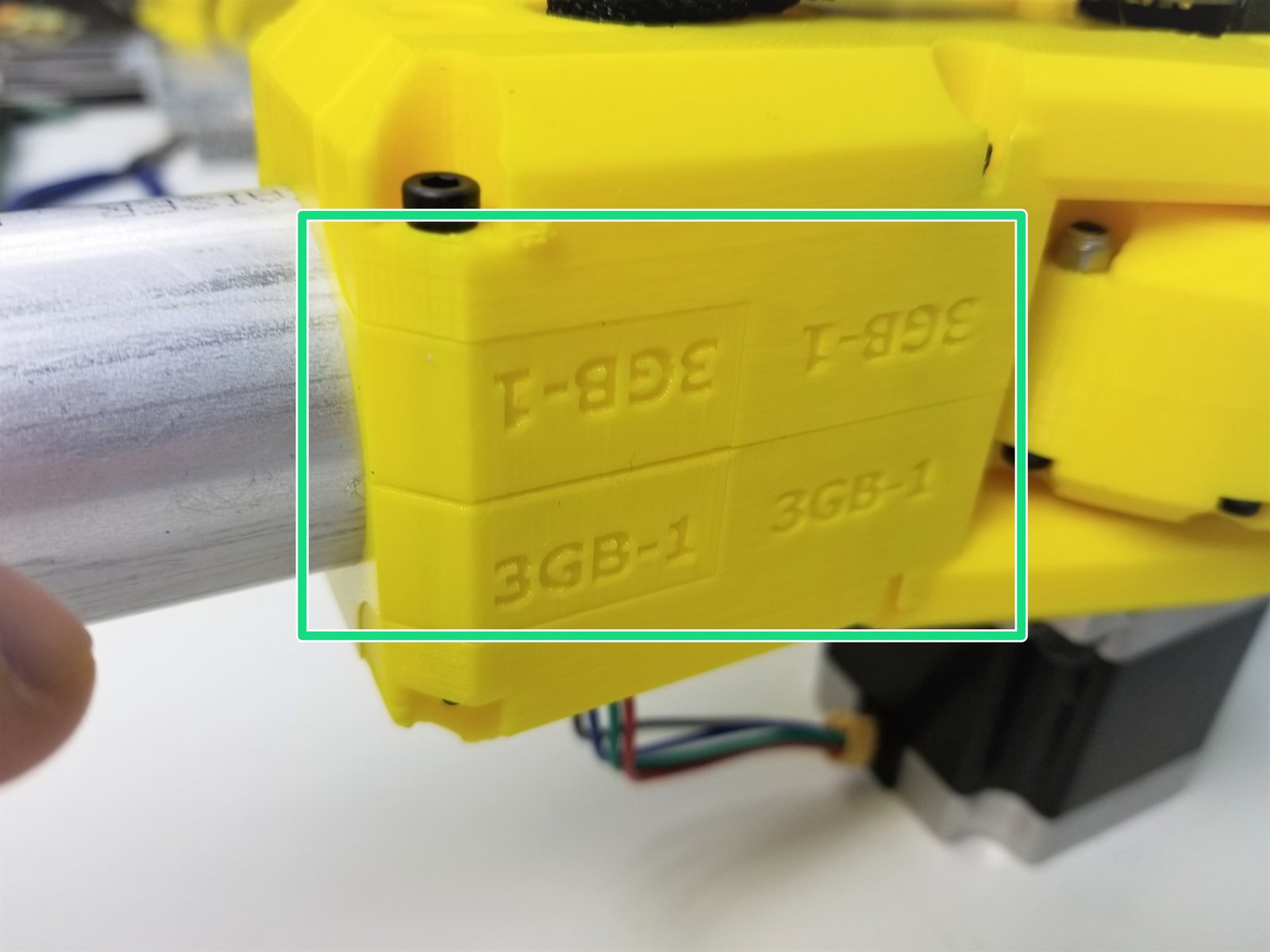
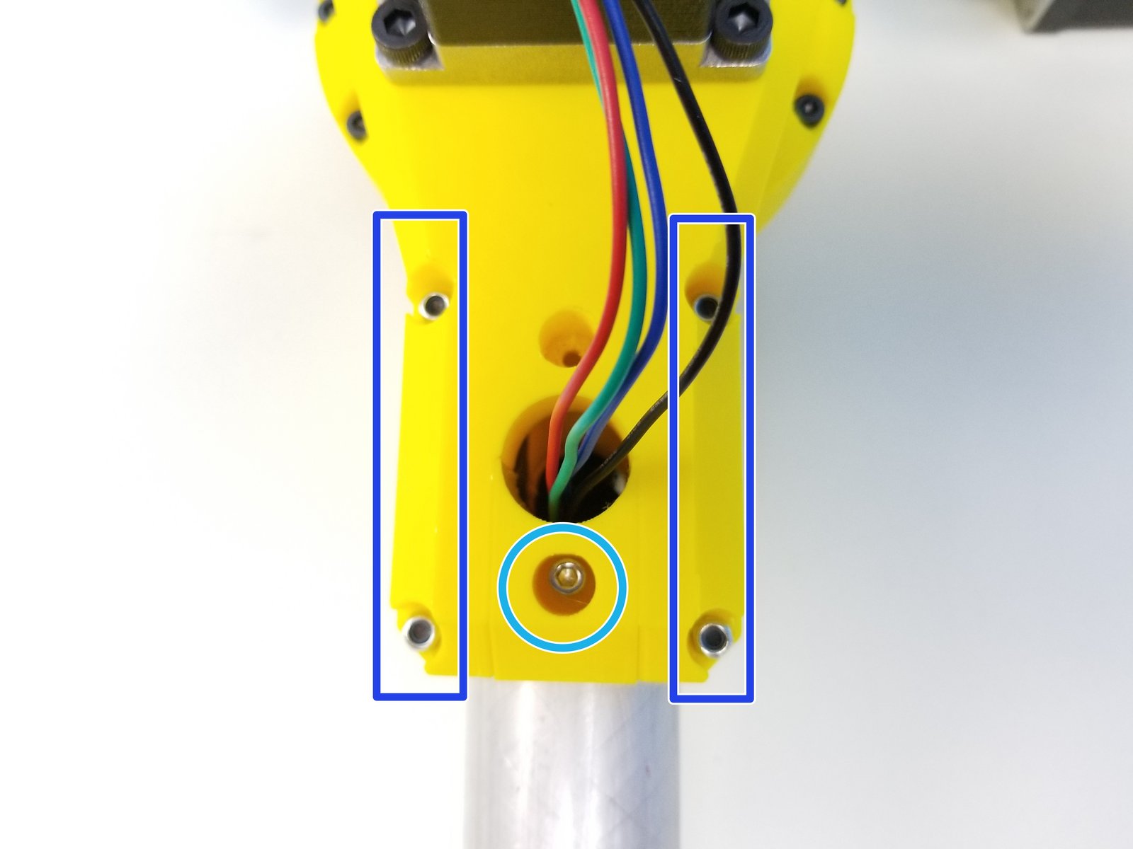
Click the large image to open full size.
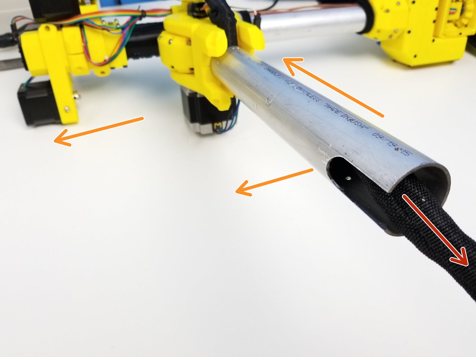
Insert the Cable Sleeve through the Pipe
Insert the Pipe into the Elbow Gearbox Bottom
- Warning:
The Bottom Single U-cut is facing the Elbow Tail {Forearm Motors}
Align the Elbow Bottom Caps as shown in the picture
Secure the alignment with M3x8mm Screws
Tighten the Pipe using the M3x45mm Screws and M3 Nylock Nuts
Step 11 Bicep Linkage - Shoulder Gearbox
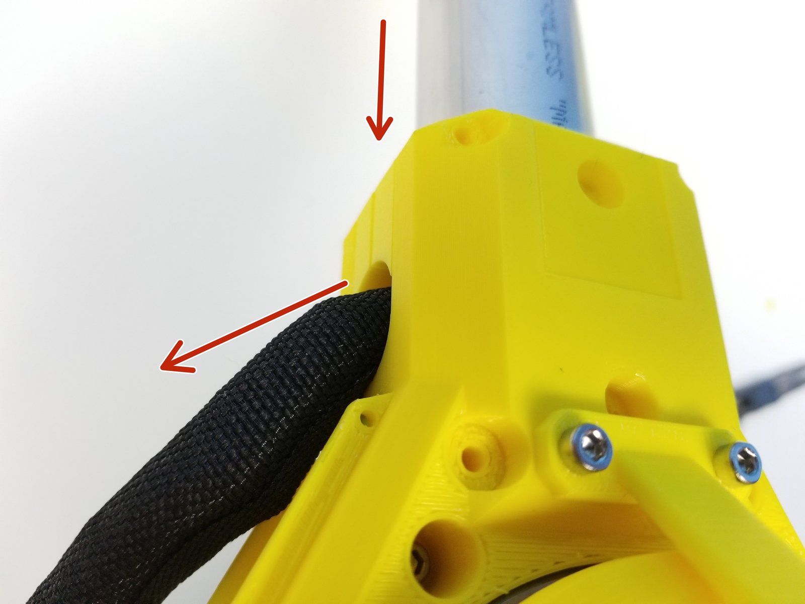
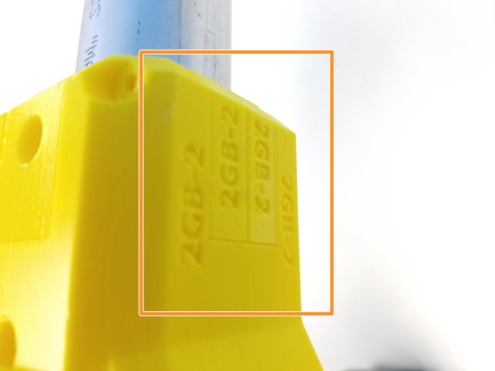
Click the large image to open full size.
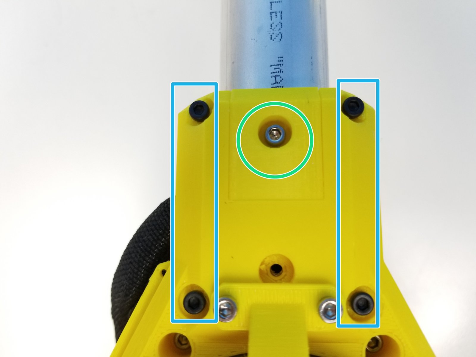
Insert the Pipe into the Shoulder Gearbox and pull the Braided Cable Sleeve out
Align the Shoulder Top Cap as shown in the picutre
Align the Cap using M3x8mm Screws on both side
Tighten the Pipe using the M3x45mm Screws and M3 Nylock Nuts
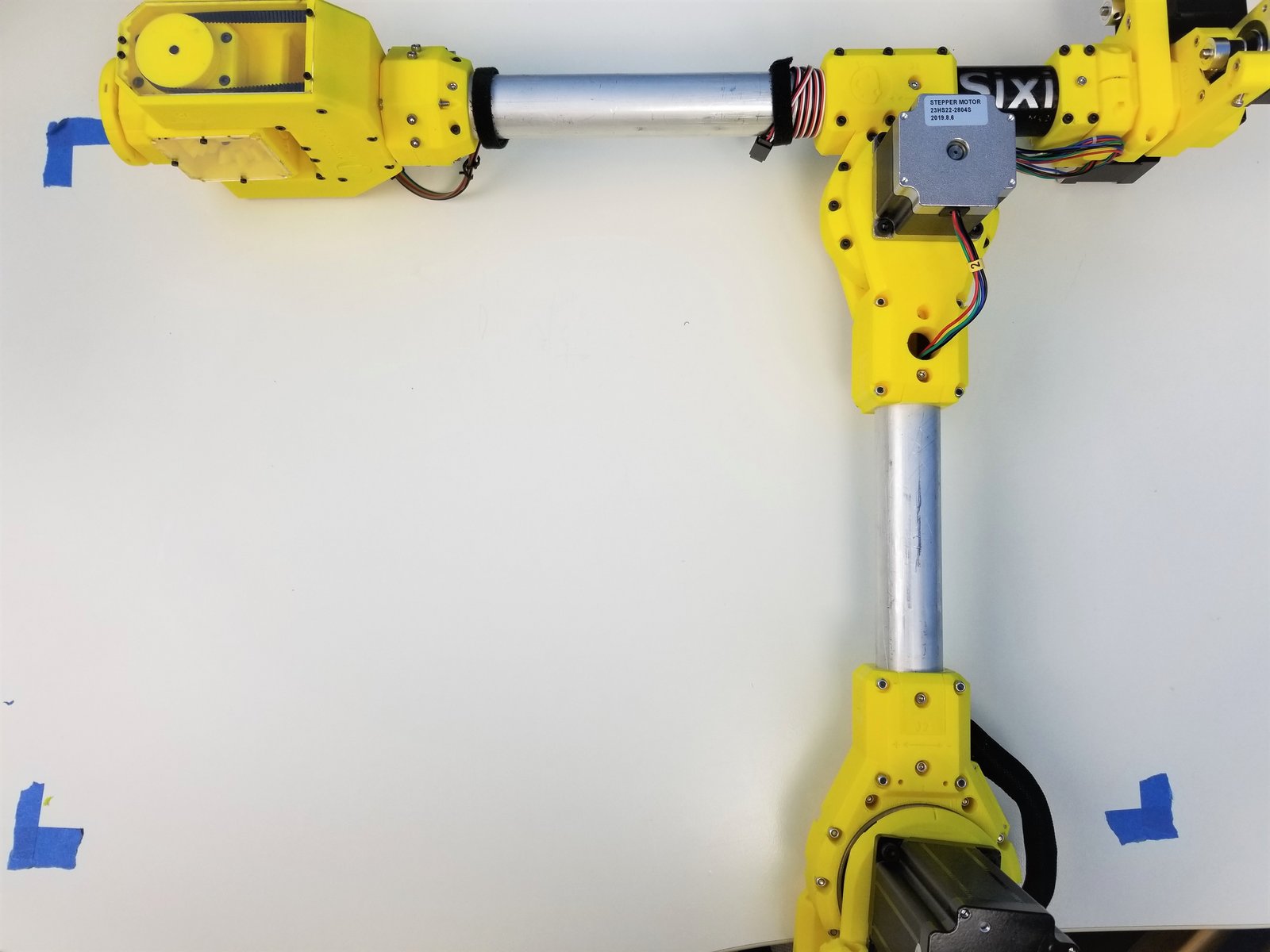
Step 12 Finish!
Click the large image to open full size.
Congratulation!!! You are so close, Get the Anchor and we will be ready to test!!