Sixi 2 robot arm
1. Electronic Case Assembly
Step 1 Tools Required
Tools required for assembling SIXI:
Alan Keys (metric): Ball End is recommended
5mm Hex Nut Driver
Needle Nose Plier
Step 2 Label and Version Guide
- Note:
Most 3D printed parts are labelled to verify the package and versions.
Step 3 How to be successful
Click the large image to open full size.
- Note:
Read each chapter before you start work. Catch confusing things early!
- Warning:
Always follow every step in order.
If a step is unclear, use the comment section below it to let us know.
- Note:
Steps may be color coded and have matching colored symbols on the pictures. A single picture could have more than one symbol.
Step 4 3D printing
If you are 3D printing parts yourself, make sure to calibrate your printer! Bad tolerances will make gearboxes either (A) sloppy or (B) so tight they don't move.
Step 5 Tools and Parts Required for This Chapter
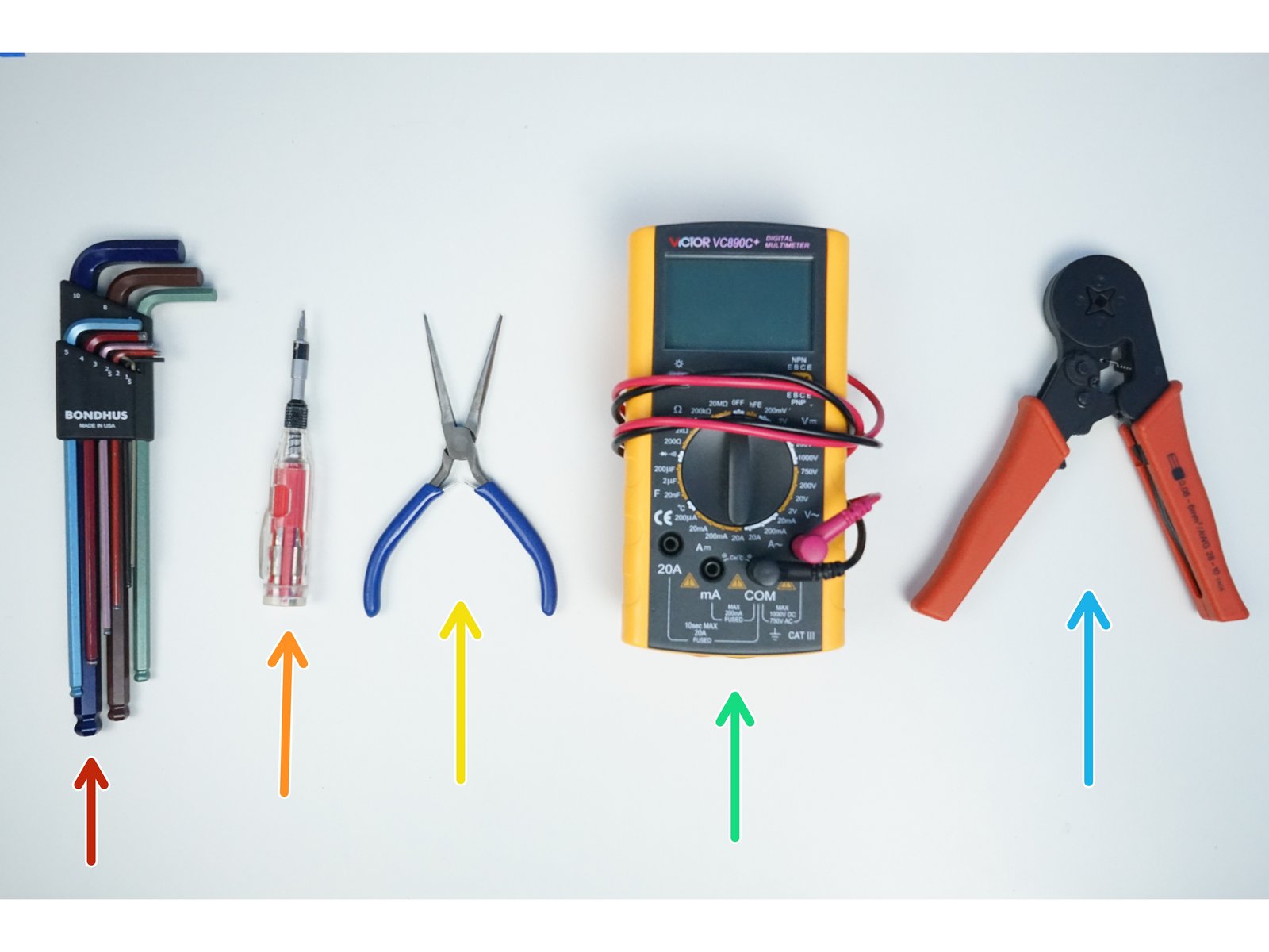
Click the large image to open full size.
[3D] Electronic Case Package
Robot Electronics
Alan Keys
Flat Screw Driver
Needle Nose Pliers
Multimeter
Ferrule Crimper (optional)
Step 6 Case Wall Mount - Parts
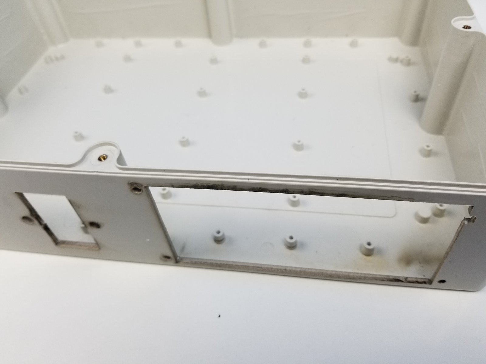
Click the large image to open full size.
- Note:
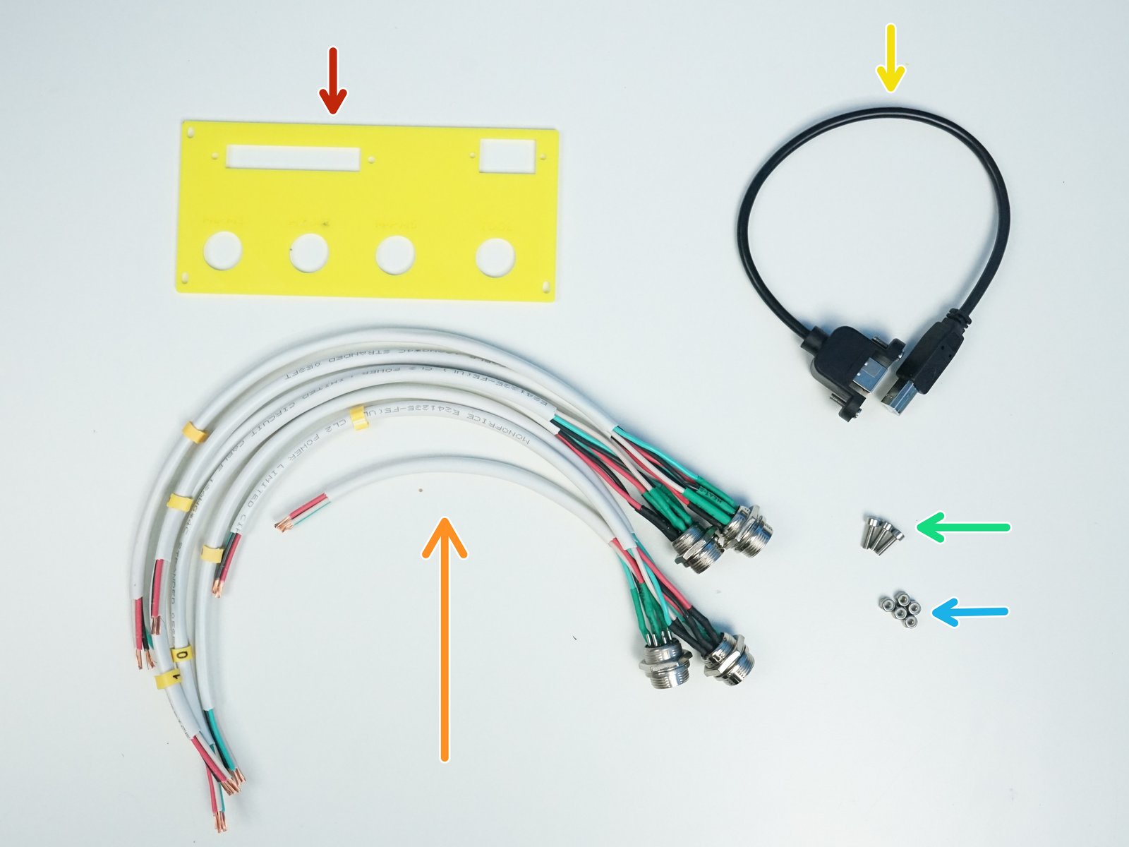
Prepare the following components:
ABS Junction Box {380x260x105mm}
[3D] - 7E-plug wall adapter
Aviation GX16-8p Cable M/O (wire assembled and numbered)
USB-B M/F Panel Mount Extension
M3x10mm Screws (x3)
M3 Nylock Nuts (x5)
Step 7 Case Wall Mount - GX16 Aviation Connectors 1
Click the large image to open full size.
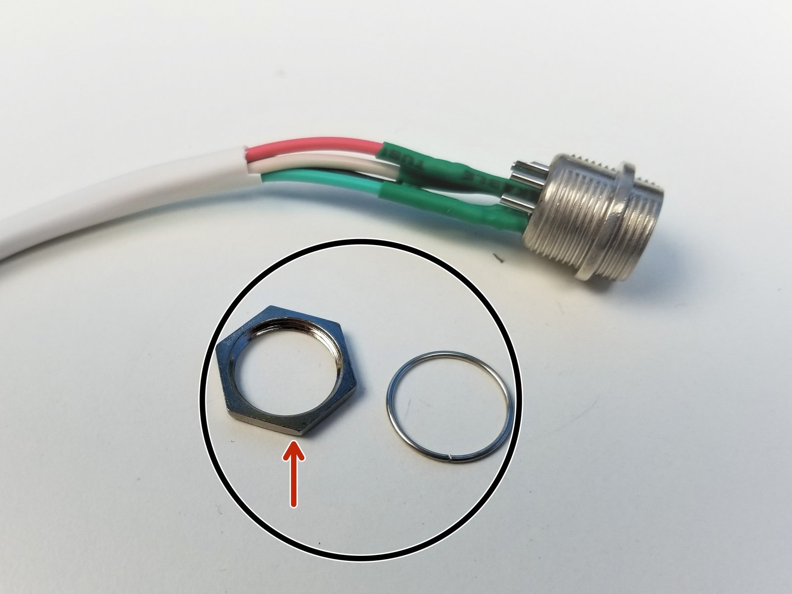
Unscrew the Wall Mount Nuts from each connectors
- Note:
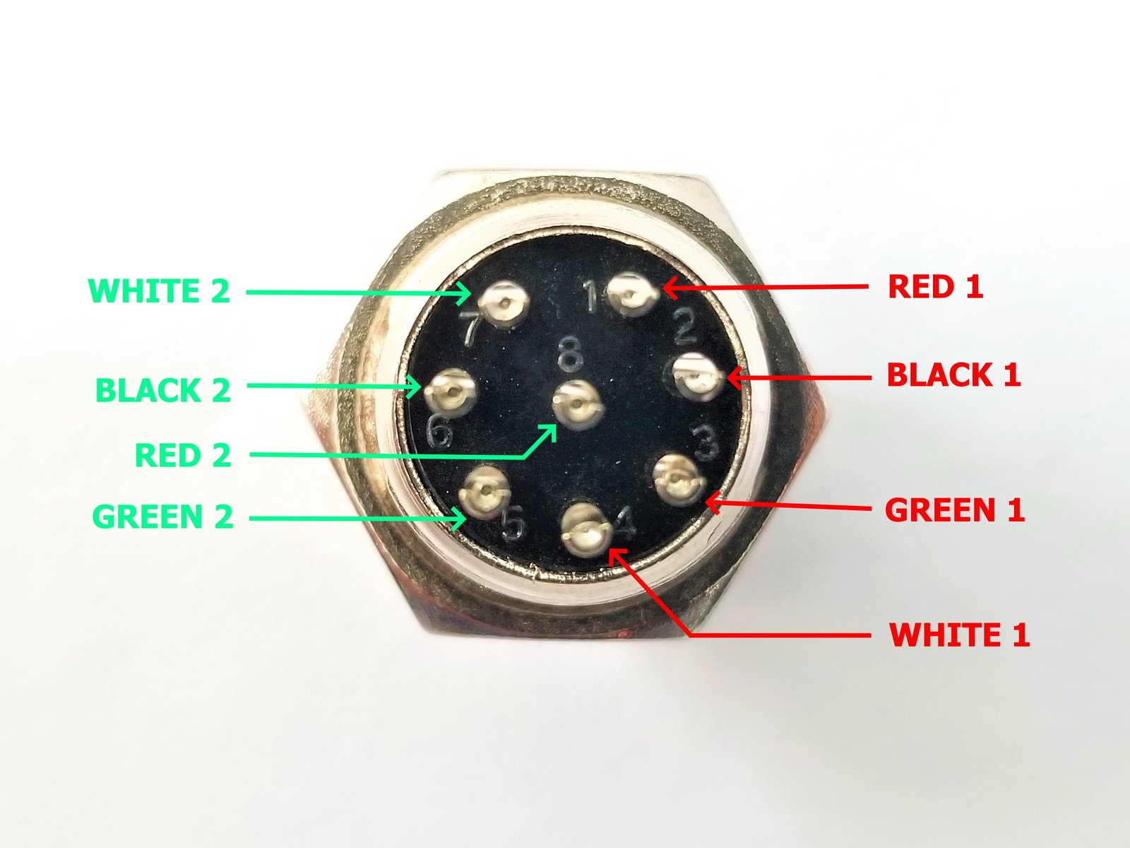
Each Connectors have 2 sets of 4pin wires soldered in this specific manner
- Note:
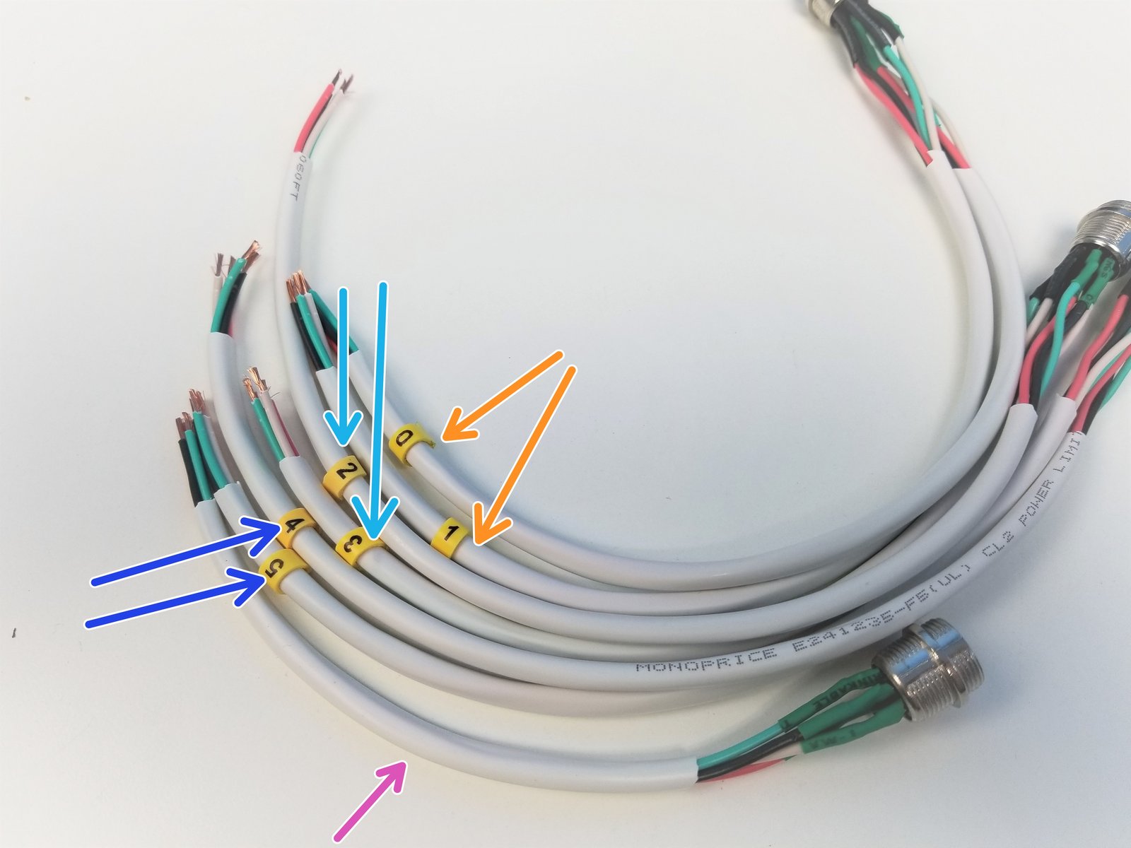
The wires are cut to length as follows:
0 & 1 = 370mm & 370mm respectively
2 & 3 = 370mm & 270mm respectively
4 & 5 = 340mm & 310mm respectively
Not Labelled = Tool --> 190mm
Step 8 Case Wall Mount - GX16 Aviation Connectors 2
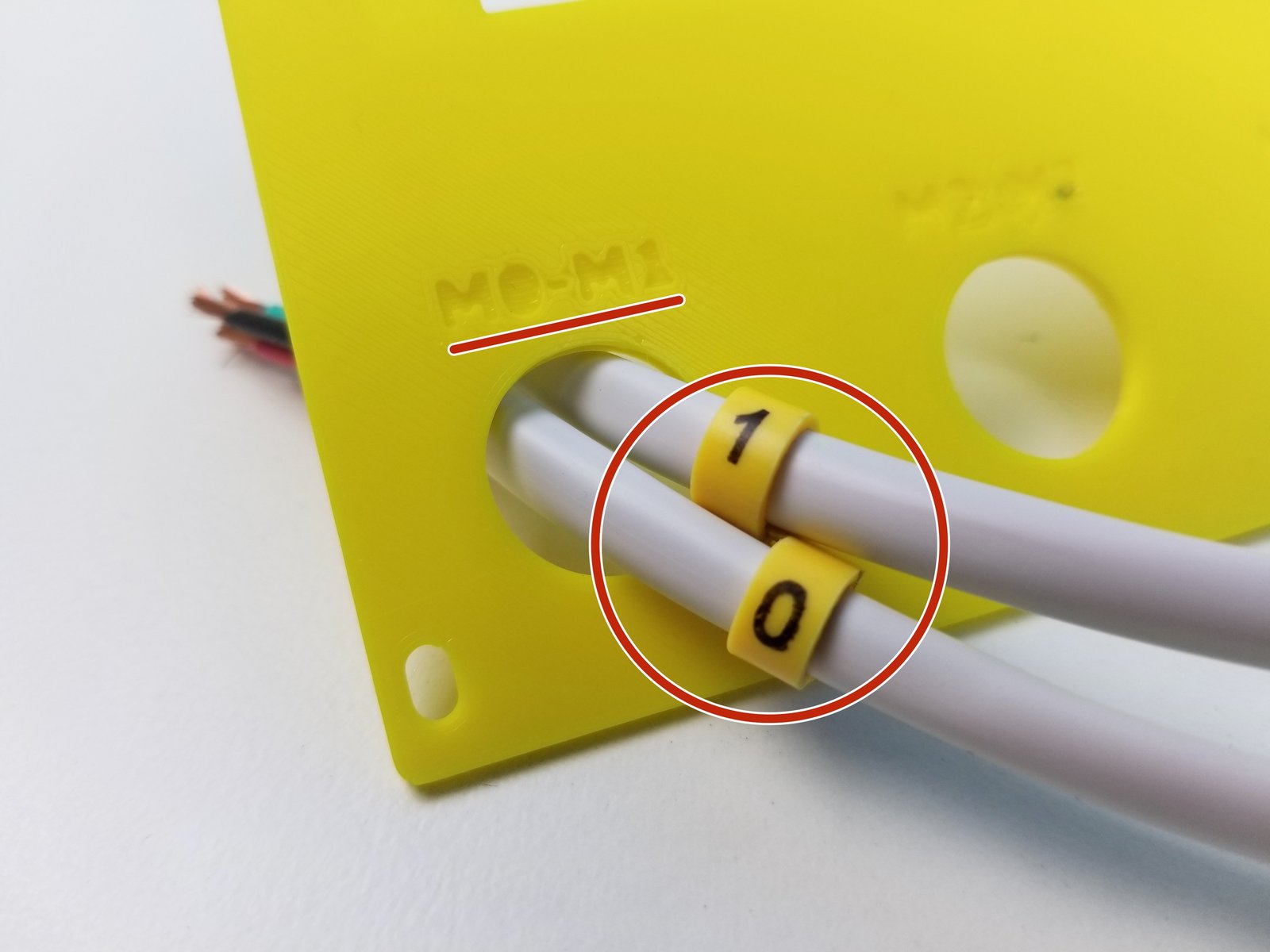
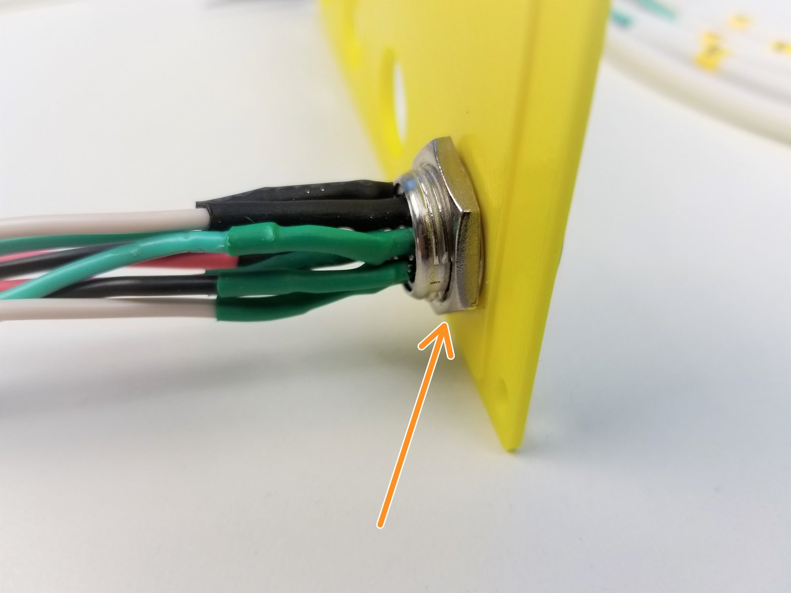
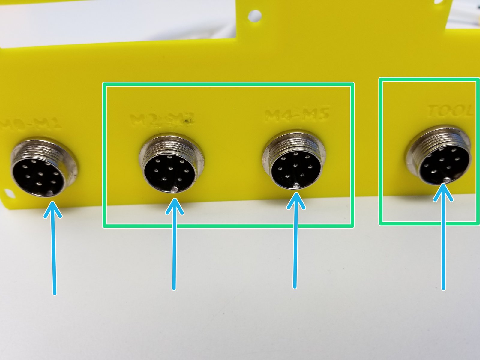
Click the large image to open full size.
- Note:
Familiarize yourself with the panel. The back side has a lip and the front side is labelled with each connector.
Feed the Cables through the Wall Adapter as labelled. Make sure the long end of the cable ends up on the back side of the panel.
Tighten the Mounting Nut that was unscrewed from the previous step
Repeat the same process with the rest of the connectors
Be sure the alignment mark on the plug to be in the bottom center
Step 9 Case Wall Mount - USB Extension Cable
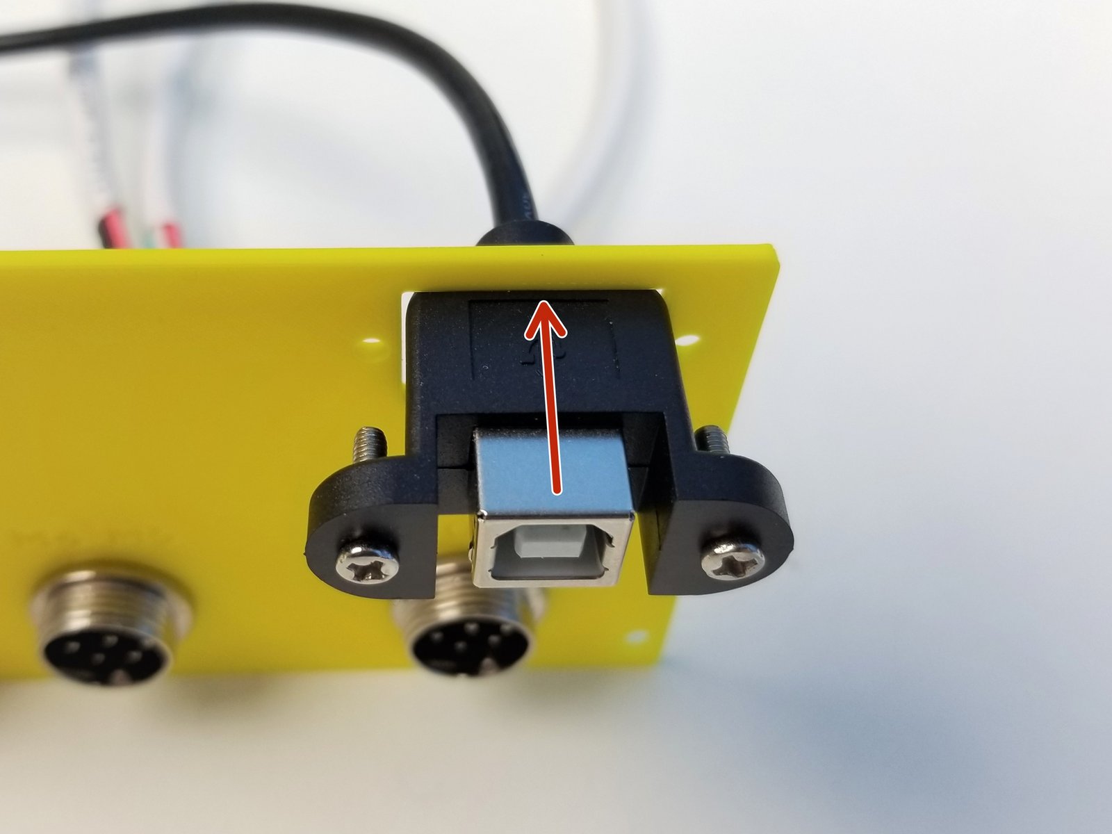
Click the large image to open full size.
- Note:
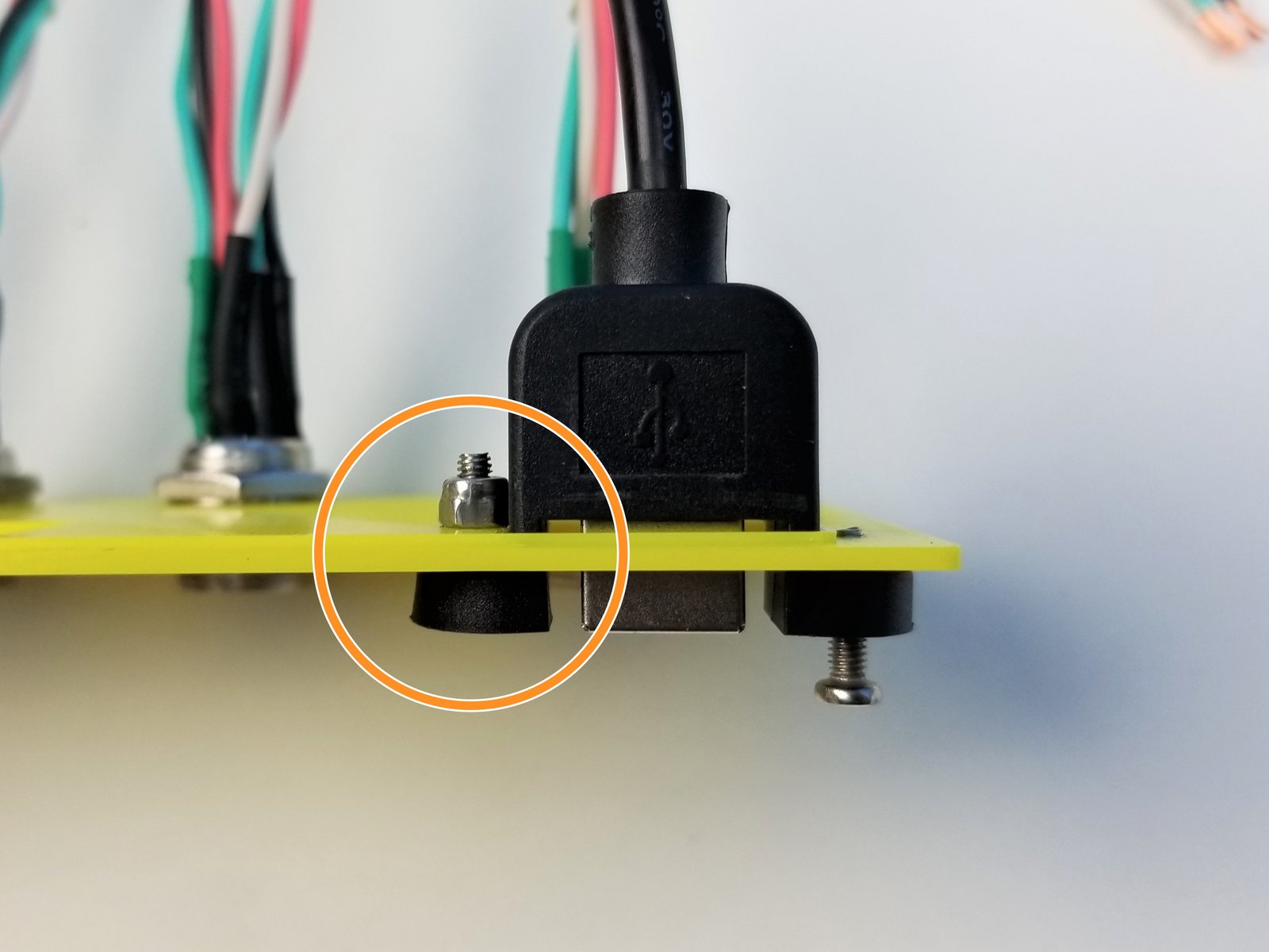
USB Extension Cable comes with M3x10mm Philip Head Screws
Feed the USB Cable through the Case Wall Adapter
Use M3 Nylock Nut to secure USB Extension Cable in place
- Warning:
Only tighten the side furthest from the edge
Step 10 Case Wall Mount - Installation
Click the large image to open full size.
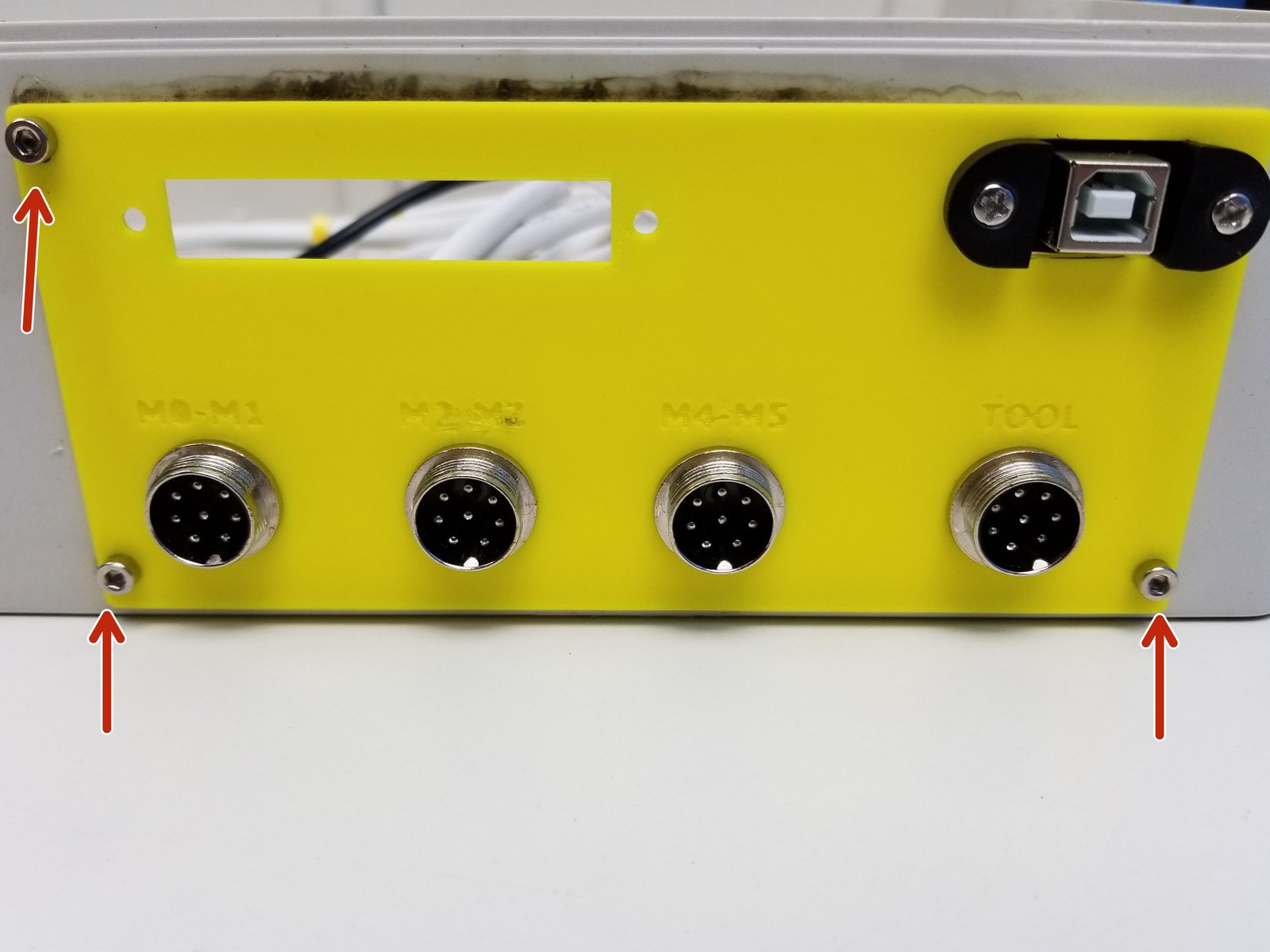
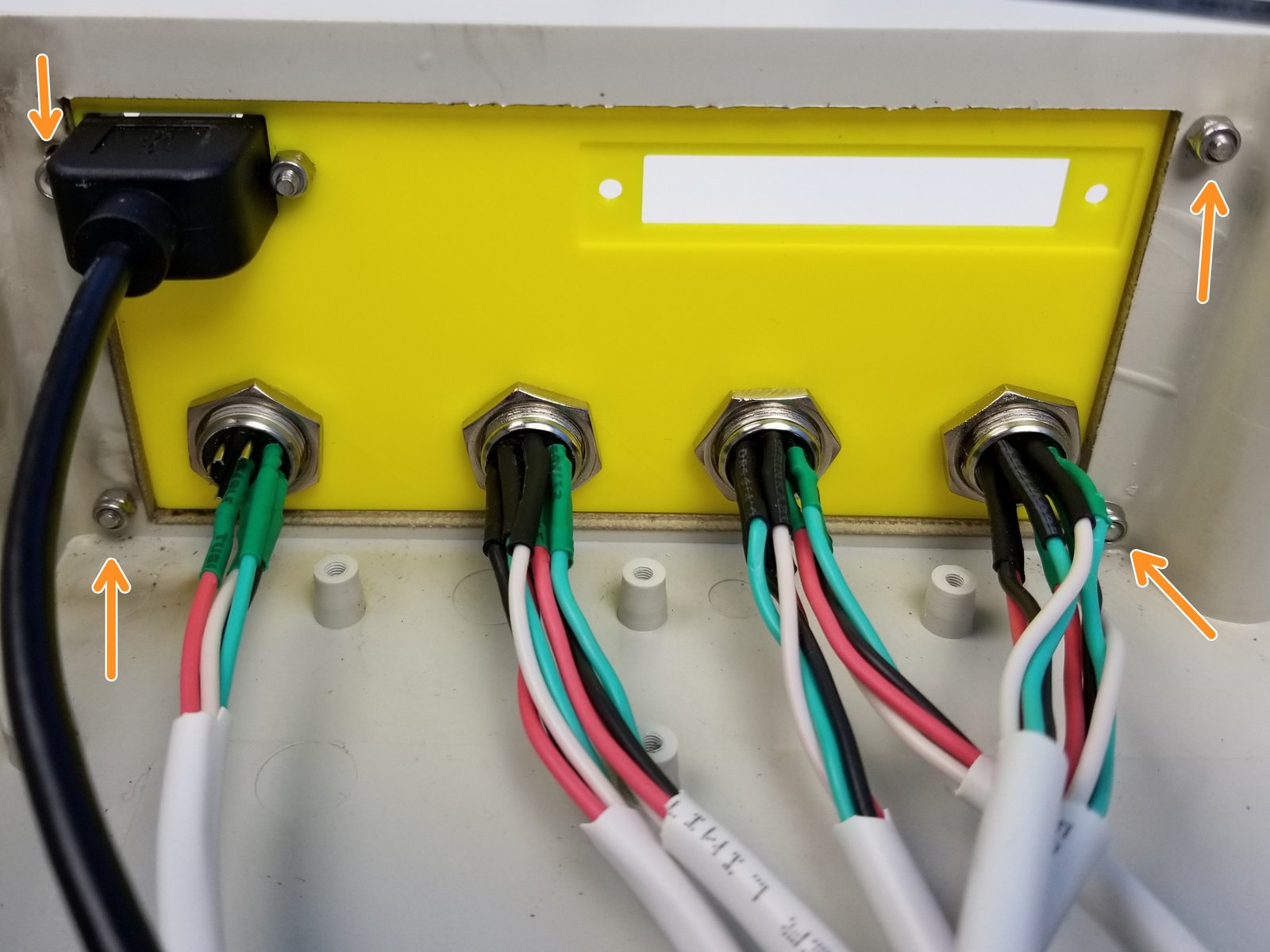
Insert the Case Wall Adapter into the Case and secure its place using the M3x10mm Screws.
Use the M3 Nylock Nuts on the inside of the case but don't tighten it too much. Case wall Adapter should be able to slide along the wall
Step 11 Power Supply Installation - Parts
Click the large image to open full size.
- Note:
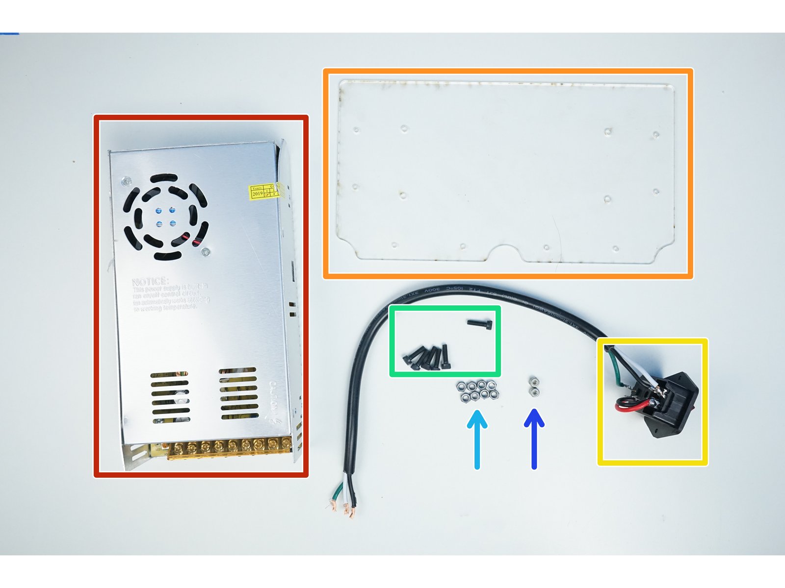
Prepare the following components:
Power Supply 24V-20A
Acrylic PSU Mounting Plate
Rocker Switch
M4x14mm Screws (x6)
M4 Hex Nuts (x8)
M4 Nylock Nuts (x2)
- Warning:
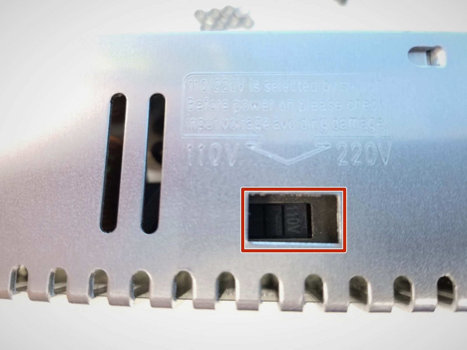
Make sure the Power Supply is set to the correct voltage, in Canada, we use 110V
Step 12 Power Supply Installation - PSU Mounting Plate
Click the large image to open full size.
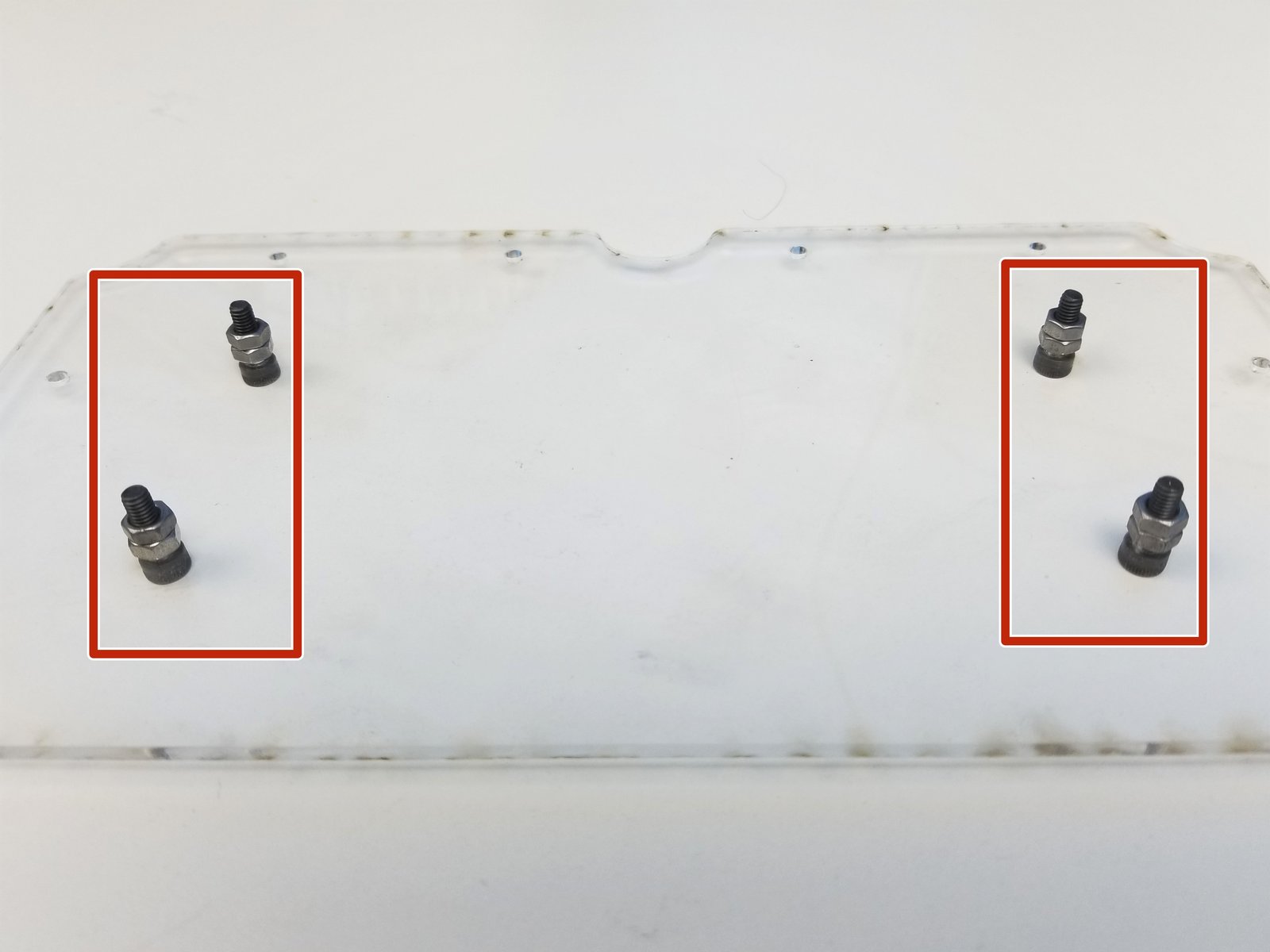
Use two M4 Hex nuts per M4x14mm Screws as spacer on the Acrylic Mounting Plate
- Note:
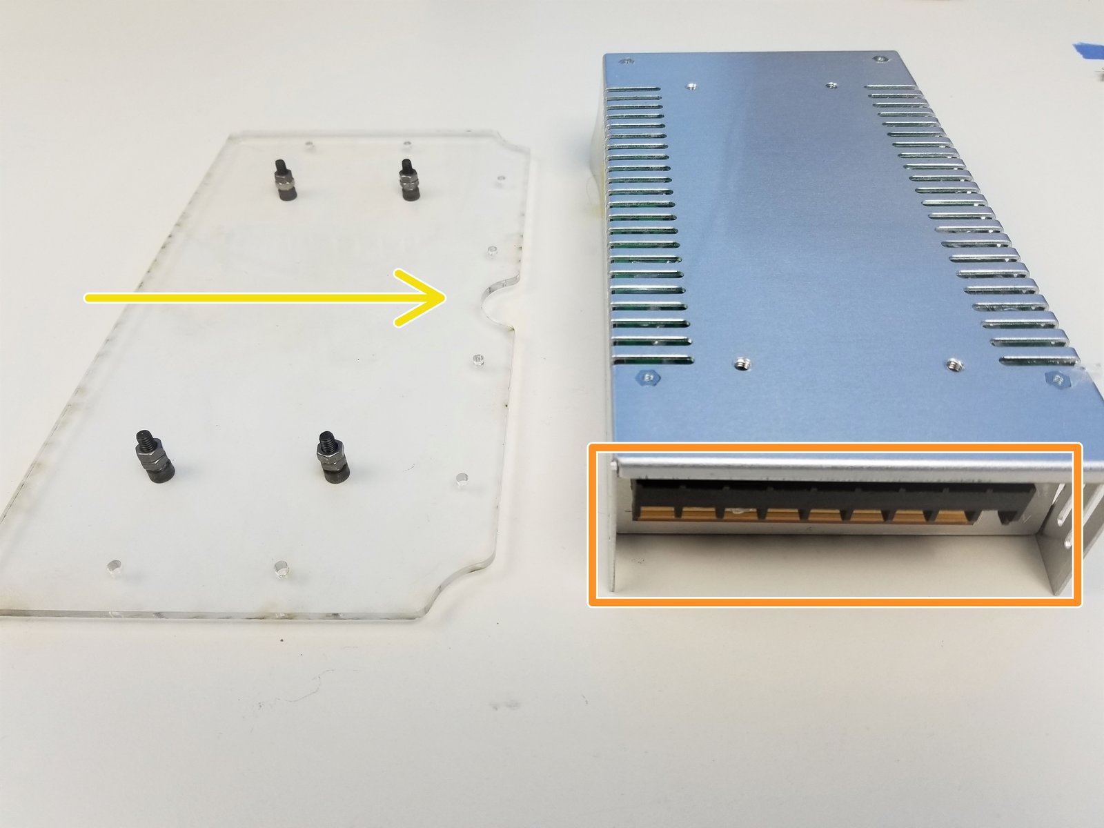
Align the PSU and the Acrylic Mounting Plate as shown in the figure exactly
Take a closer look on the Screw Terminal of PSU
Take a closer look on the "Half Moon" cut on the Plate
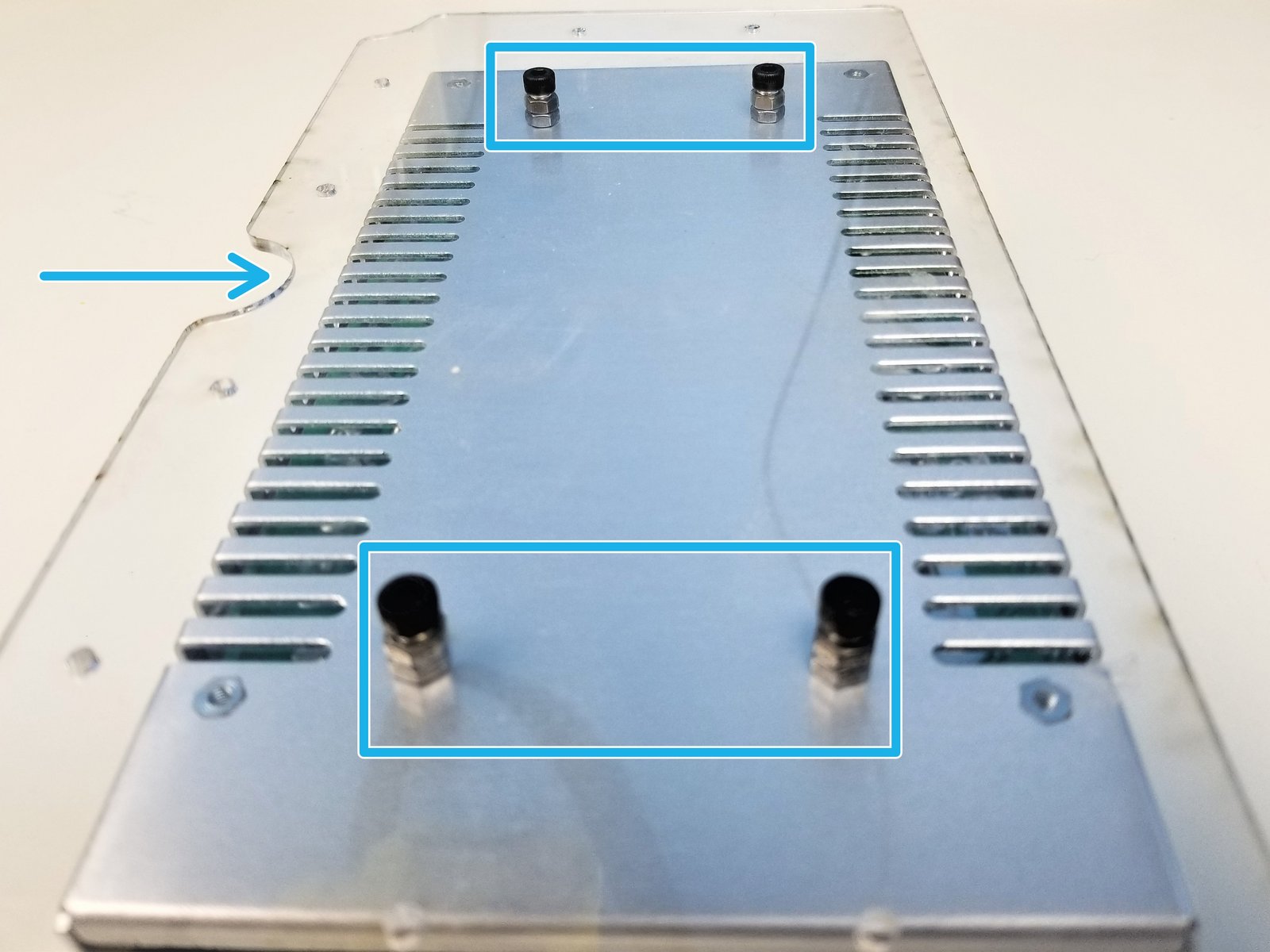
Flip the Acrylic Mounting Plate on to the PSU
- Warning:
DON'T tighten 1 screw all the way at a time, this will cause the plate to flex and cause it break
Step 13 Power Supply Installation - Rocker Switch Installation
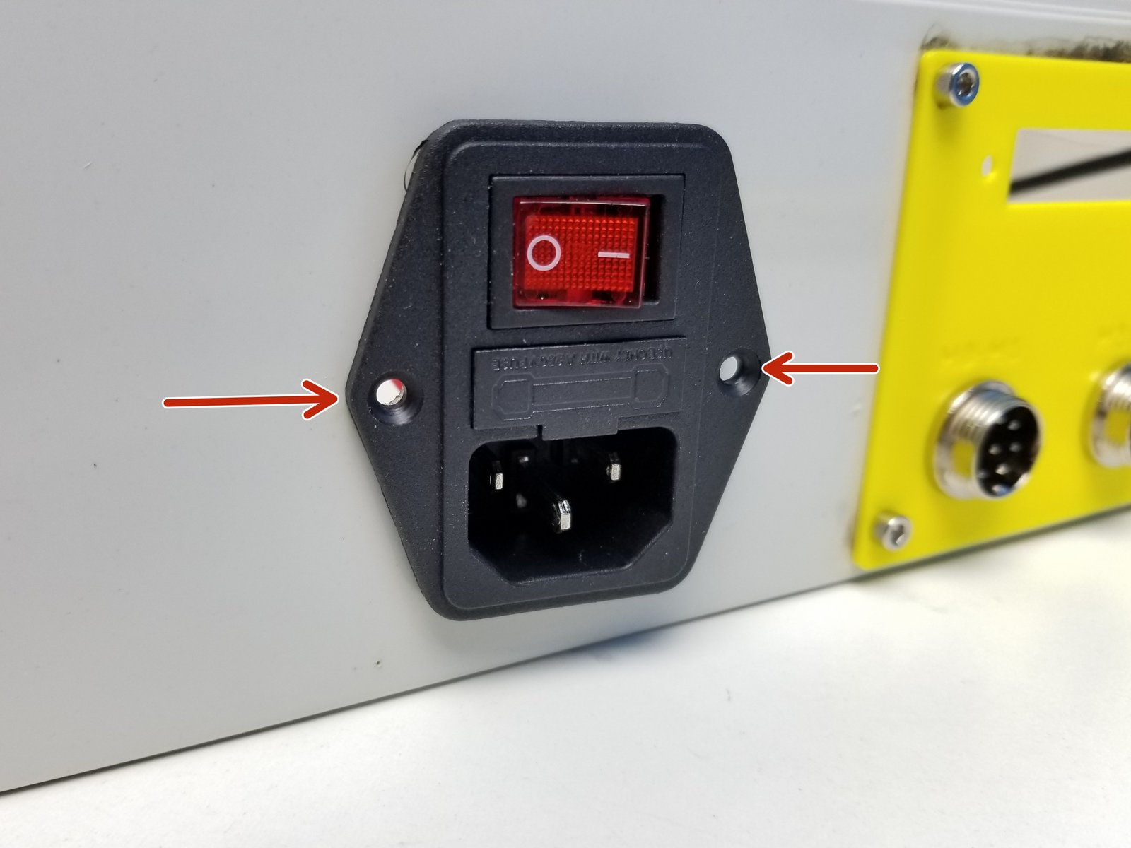
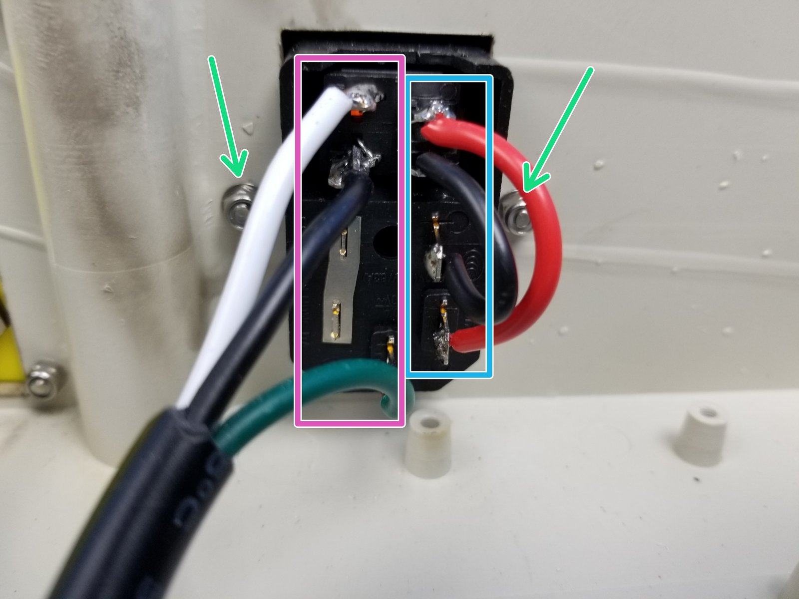
Click the large image to open full size.
Insert the Rocker Switch into the Machined Case.
- Warning:
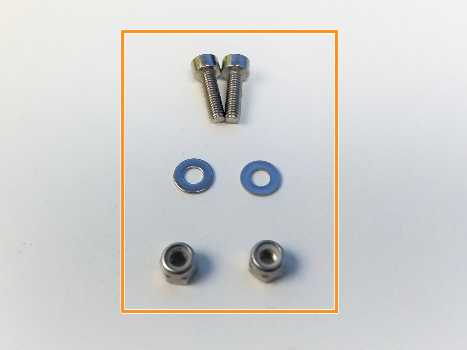
Some version of Rocker Switch has smaller mounting holes
if this is the case, use the M3x10mm Screws, Washers and Nylock Nuts
If not, use M4x14mm Screws and M4 Nylock Nuts
Secure the Rocker Switch with the fasteners
- Note:
Notice the Soldering Patterns AND Length
18AWG Power Wires 65mm long
3 Wire Power Cable 365mm long
Step 14 Power Supply Installation - Rocker Switch Test
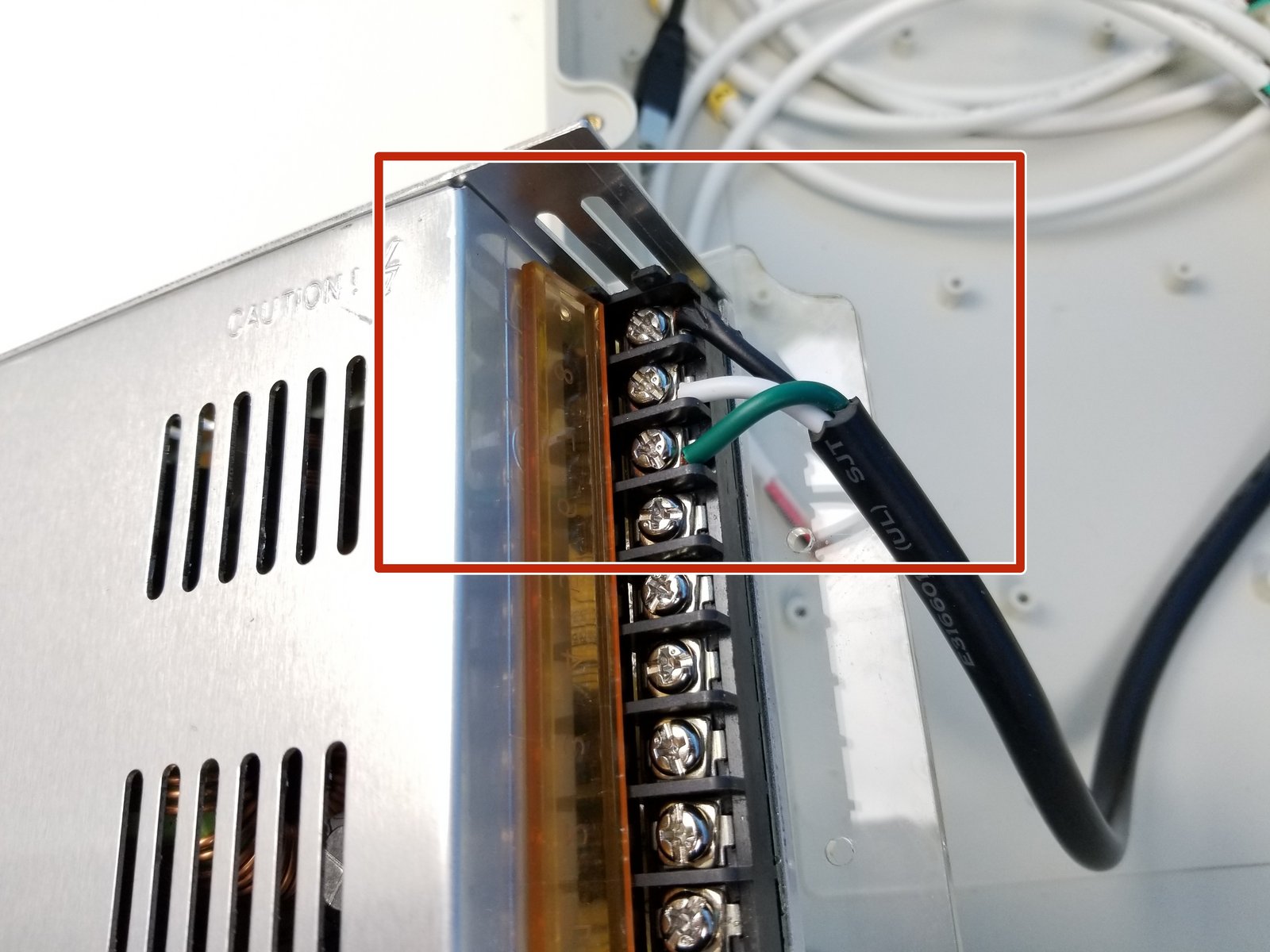
Click the large image to open full size.
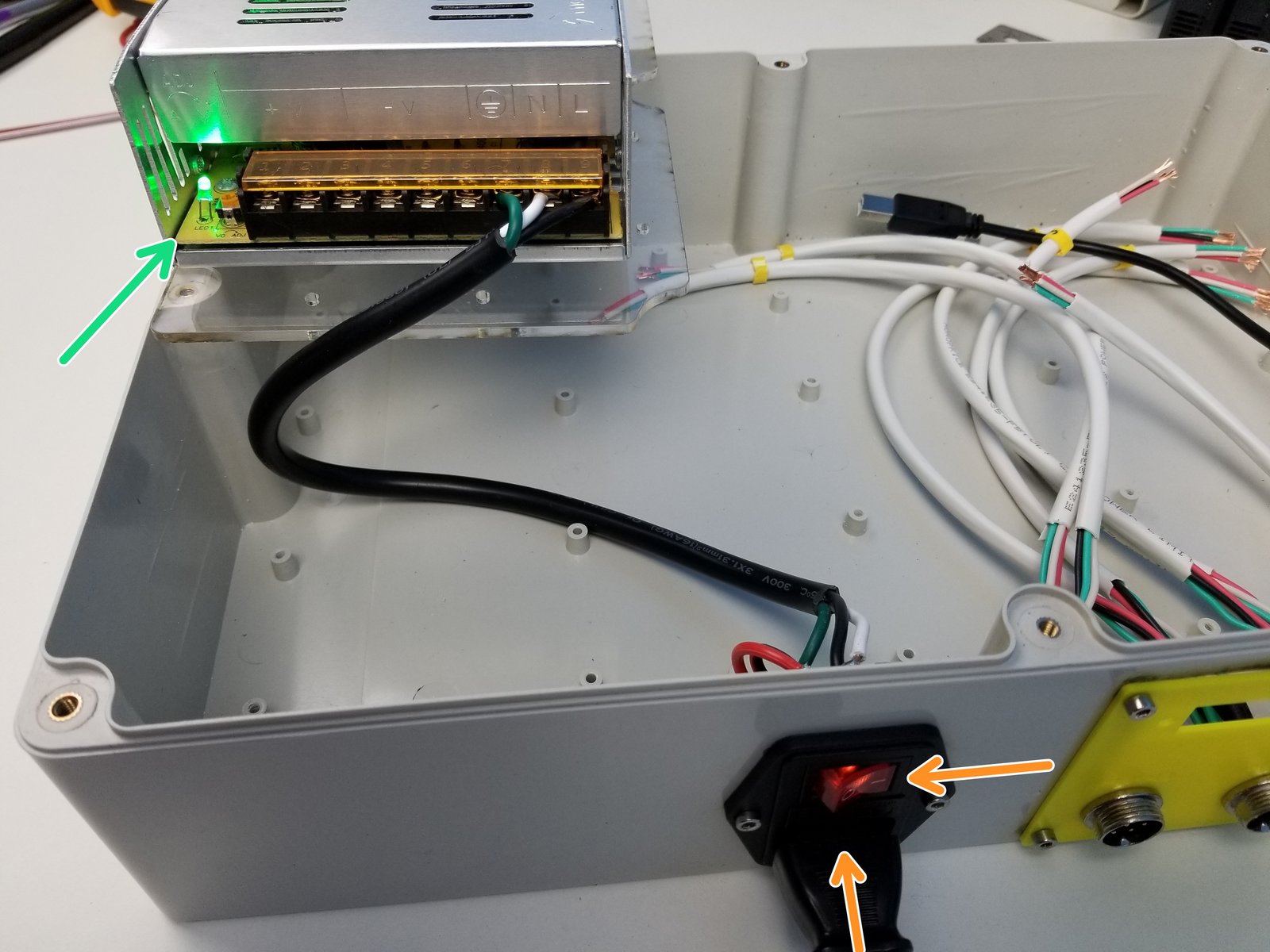
Secure the Power Cable to the PSU Screw Terminals
Test the Rocker Switch and PSU by connecting the Power Plug and turning the Switch ON
- Warning:
Be careful to NOT touch the screw terminals with your bare hands.
If the Green LED light turns on, it's a good sign
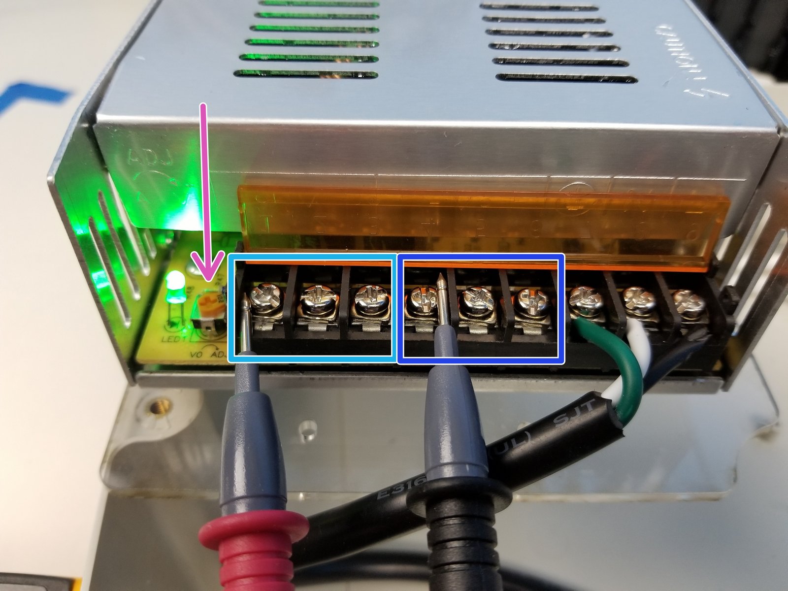
Use the Multimeter to make sure the output voltage is approximately 24V, adjust using the Philip Head Screw
Left 3 terminals are Positive Output
Middle 3 terminals are Ground/Negative Output
Once test is successful, Turn off the Power using the Switch and unplug the Power Plug
Step 15 Arduino Mega Shield Introduction
Click the large image to open full size.
- Note:
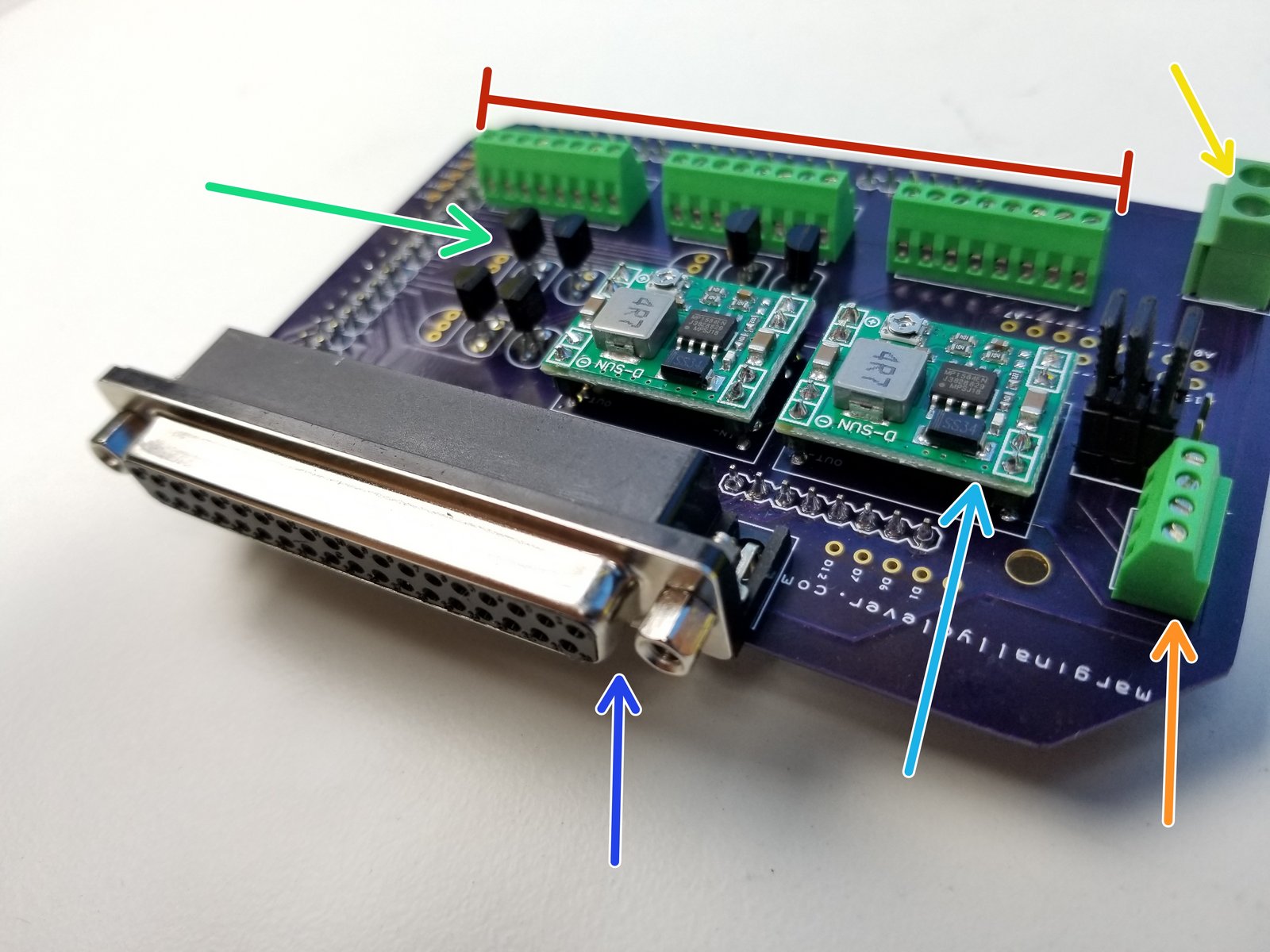
This custom Arduino Mega Shield can be ordered directly and contains the following parts:
Screw Terminal 8p - 2.54mm (x3)
Screw Terminal 4p - 2.54mm (x1)
Screw Terminal 2p - 3.5mm (x1)
NPN Transistor 2N2222A (x6-9)
Voltage Regulator MP1584EN (x2)
D-SUB F-Conn right-angle 37p
- Warning:
The voltages in the MP1584EN must be adjusted before we connect this to the Arduino Mega. Incorrect voltage could damage the electronics.
Step 16 Power Supply Installation - Arduino Mega Shield Test
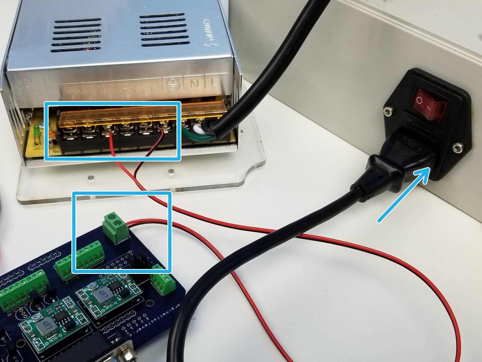
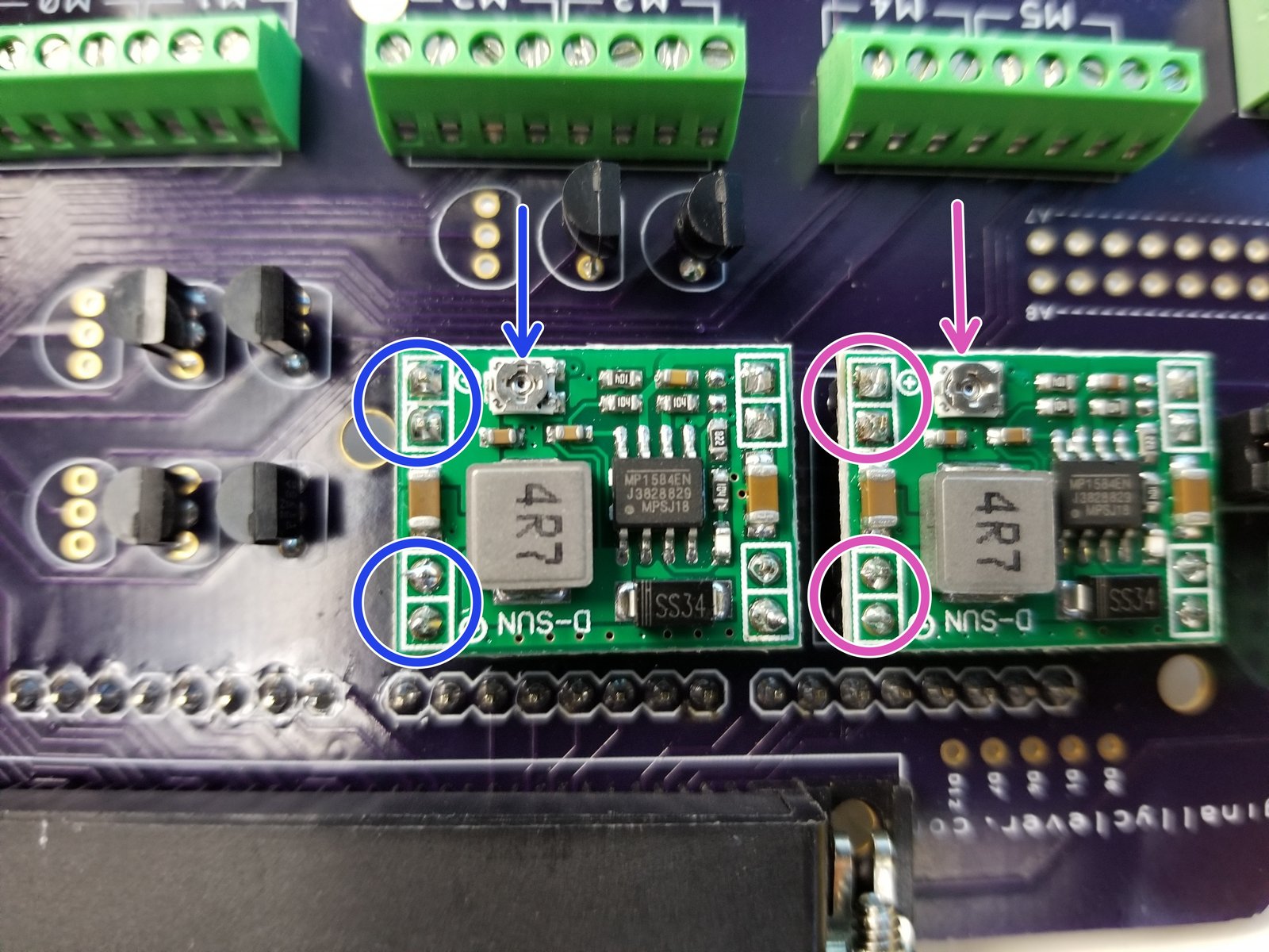
Click the large image to open full size.
- Note:
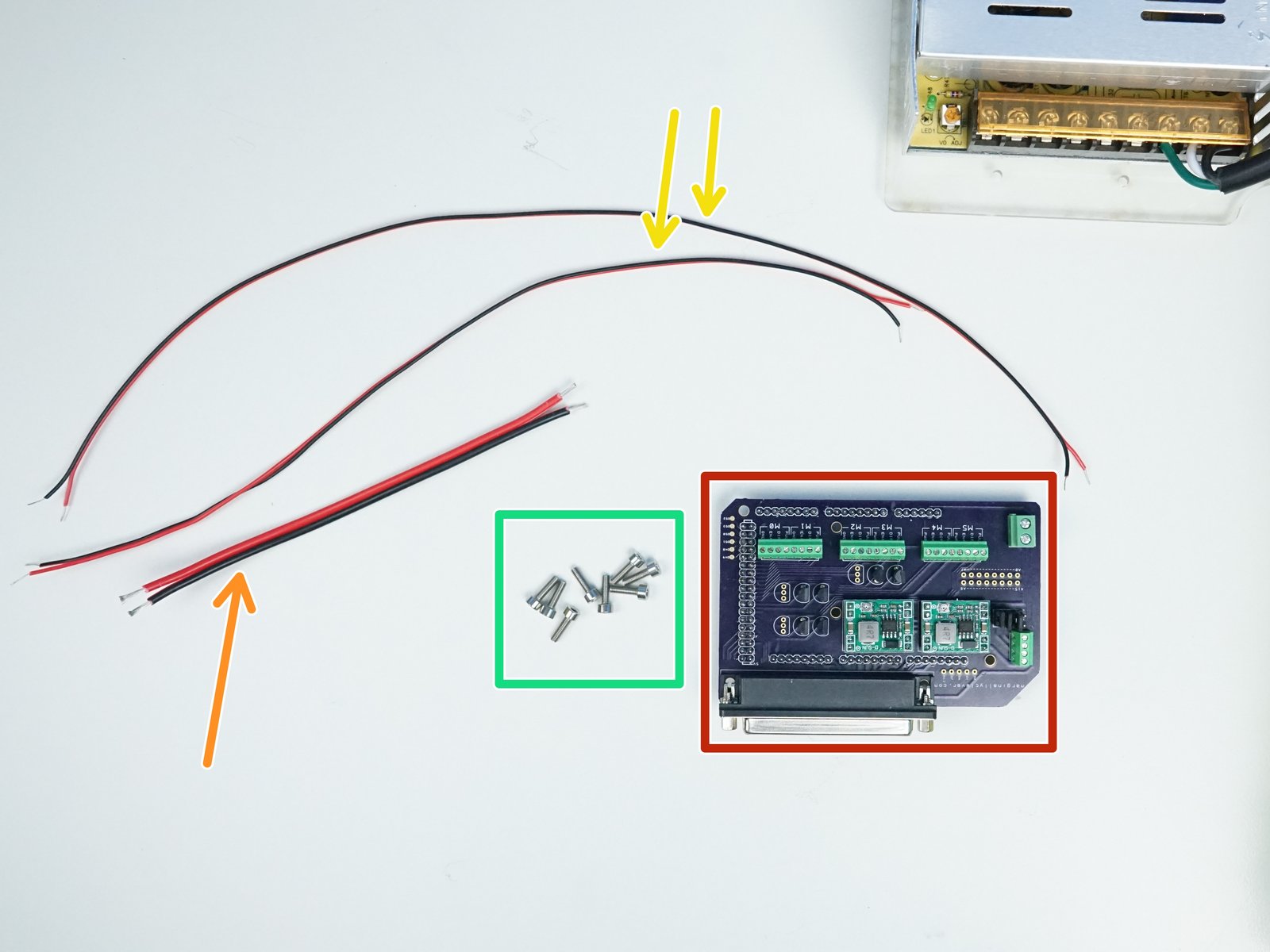
Prepare the following components:
Arduino Mega Shield
2-Wire Power Cable 18AWG - [160mm]
2-Wire Power Cable 22AWG - [335mm & 420mm]
M3x8mm Screws (x8)
Connect the PSU and Mega Shield using the 22AWG 420mm long wires. Connect the plug to the Switch and turn the power ON
Test the LEFT MP1584EN output voltage to be 6V or whichever voltage your gripper servo needs, adjust using the potentiometer
Test the RIGHT MP1584EN output voltage to be 10 -12V for powering Arduino Mega .
Step 17 Power Supply Installation - Final Installation
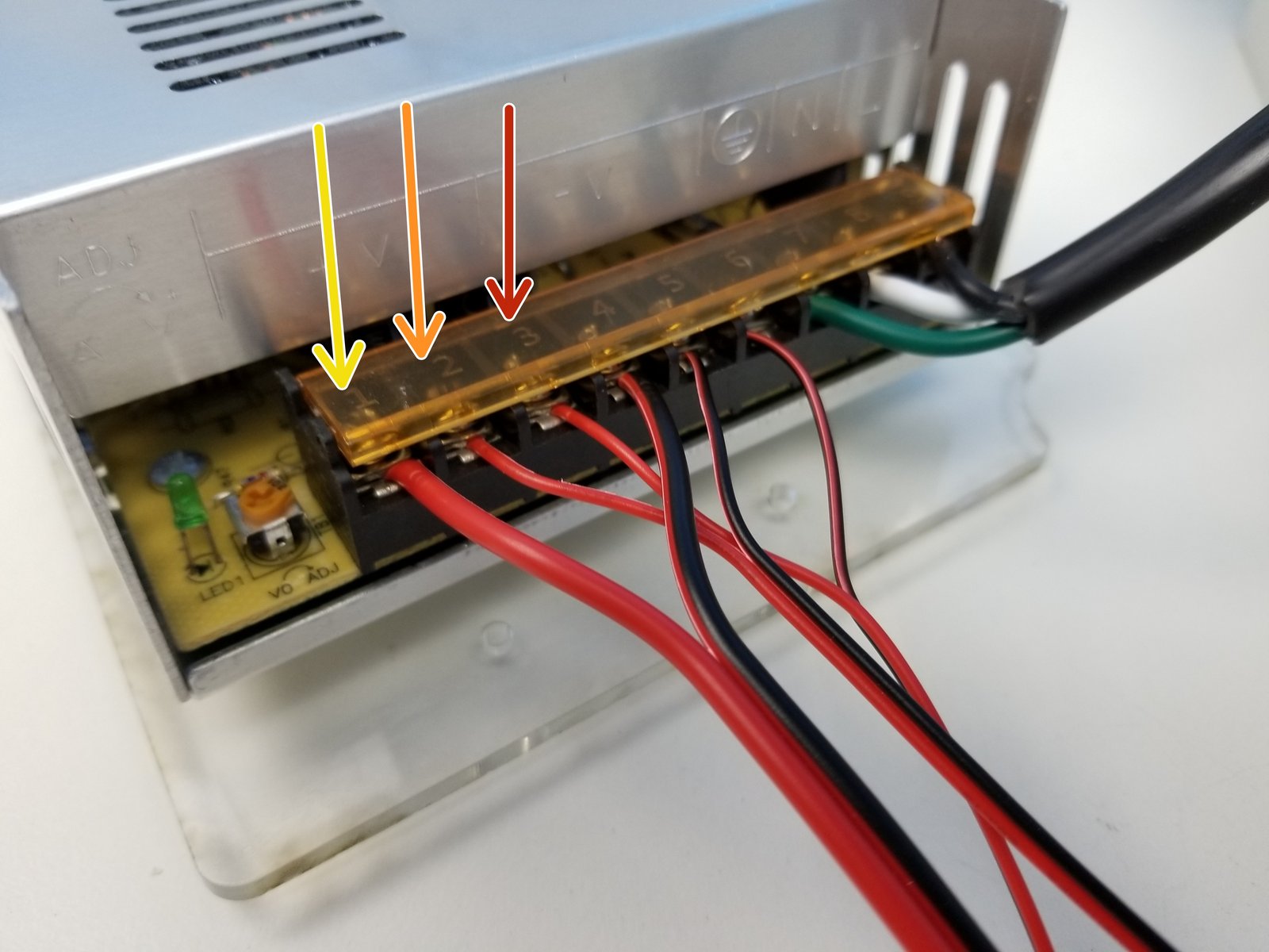
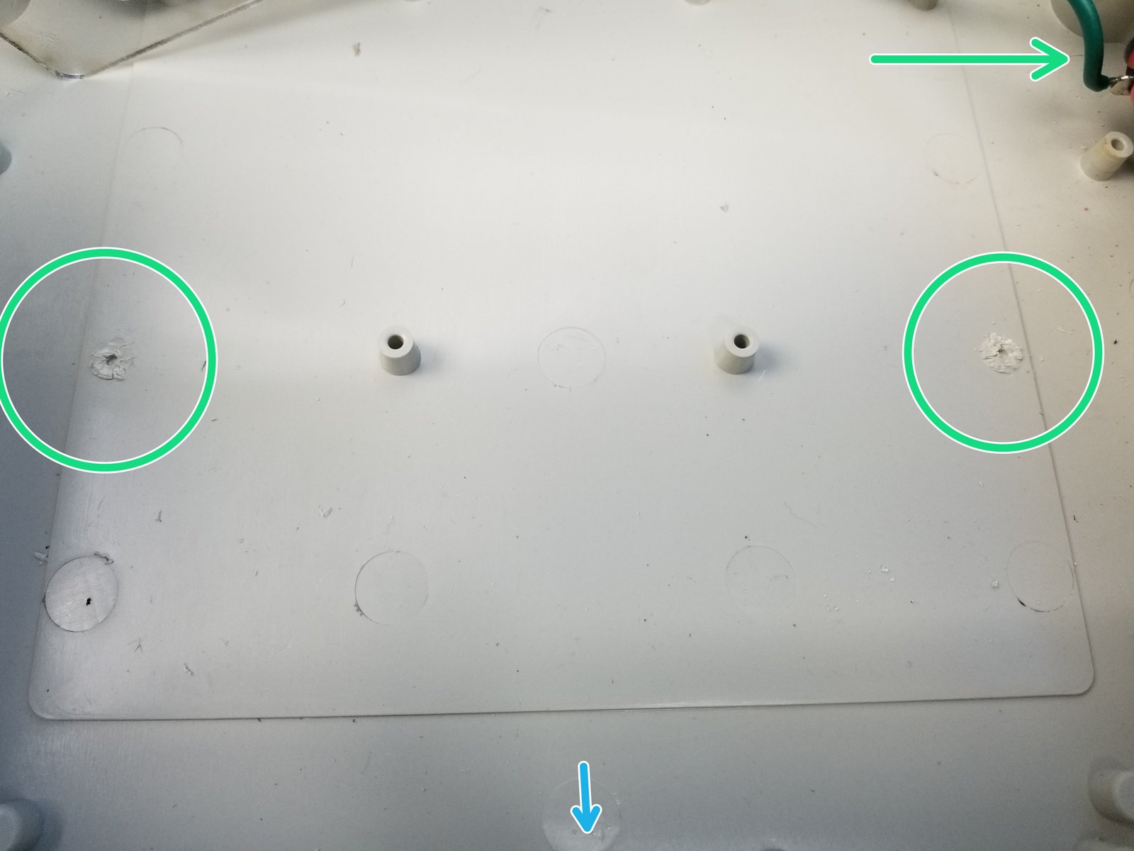
Click the large image to open full size.
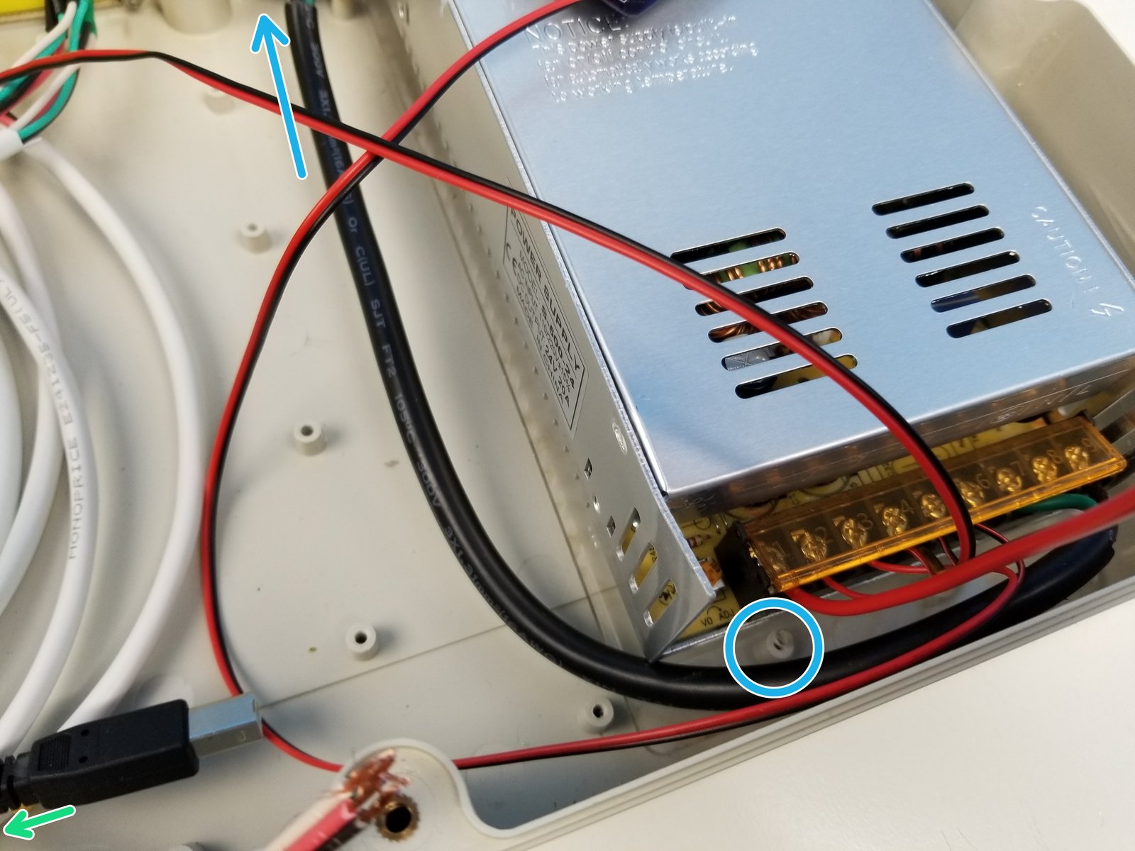
Connect the rest of the power Wires
Small Stepper Driver Wires (22AWG 335mm long)
Big Stepper Driver Wires (18AWG 160mm long)
Using a wire cutter to snip two pegs positioned with respect to the Rocker Switch on the top right corner of the picture.
Align the Half Moon slot and secure the mounting plate to the Case using M3x8mm Screws in the available spots around PSU.
Step 18 Arduino Installation - Parts
Click the large image to open full size.
- Note:
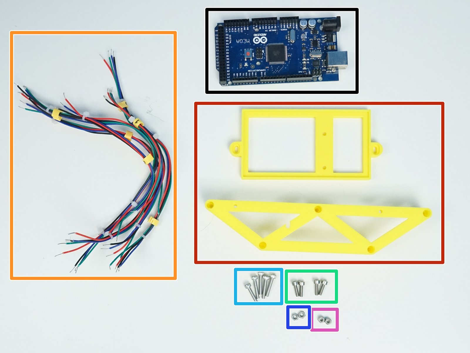
Prepare the following components:
Arduino Mega 2650
[3D] Arduino Tray and Standoffs
4-Wire Signal Cable 22AWG {for Motor}
M3x10mm Screws (x4)
M3x16mm Screws (x5)
M3 Hex Nuts (x2)
M3 Nylock Nuts (x2)
Step 19 Arduino Installation - Signal Cable Lengths
Click the large image to open full size.
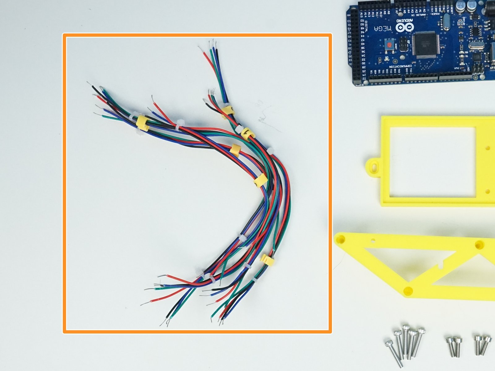
Length of each 4-pin 22AWG wires are listed as below:
0 -> 210mm
1 -> 210mm
2 -> 200mm
3 -> 165mm
4 -> 185mm
5 -> 225mm
Step 20 Arduino Installation - Standoff
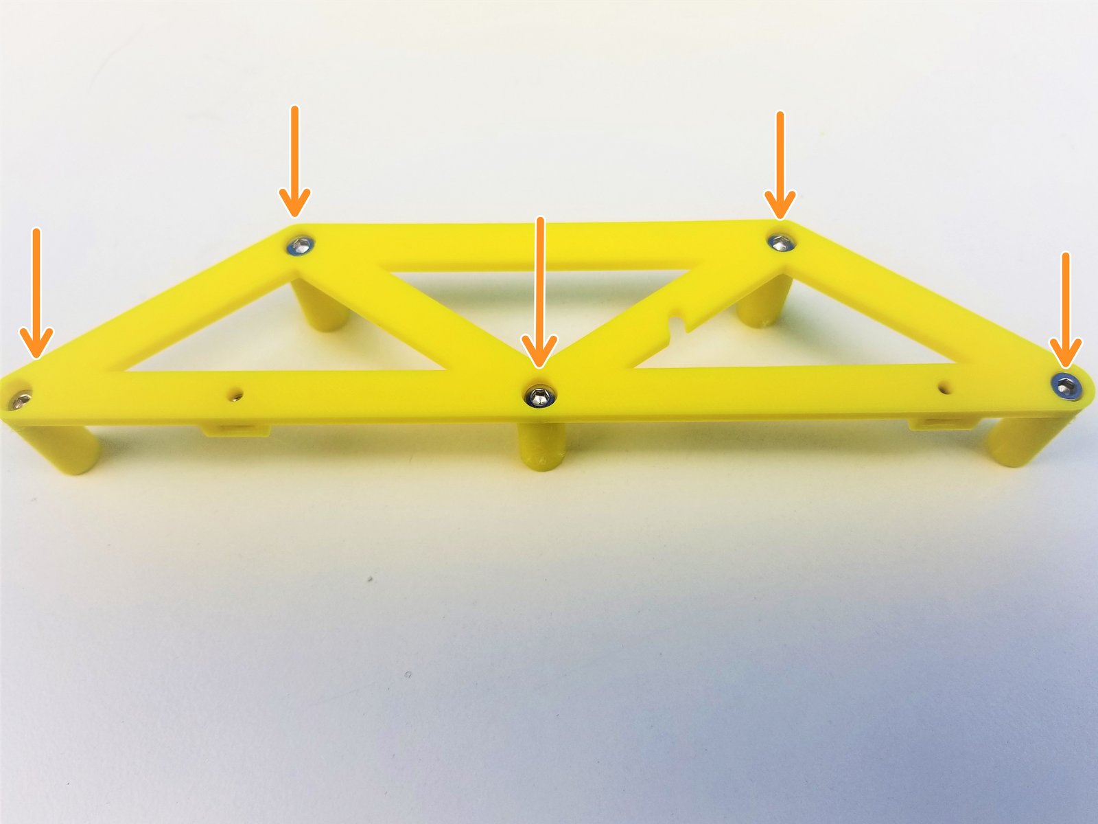
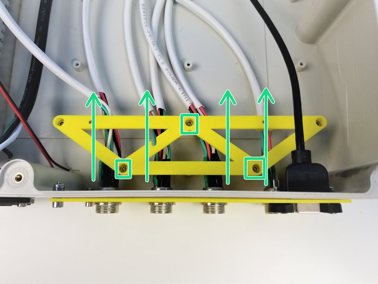
Click the large image to open full size.
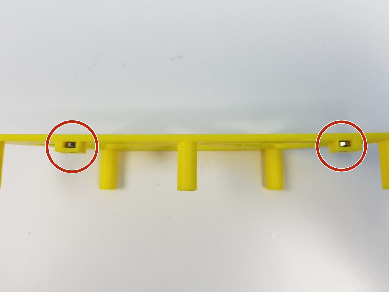
Insert M3 Hex Nuts in the side slot of the Arduino Standoff
Partially screw in M3x16mm Screws for easier assembly
- Note:
Secure the Standoff to the Case by tightening the Screws in place.
Notice the Orientation of the Standoff as well as the position of the cables relative to the pegs of the Standoff
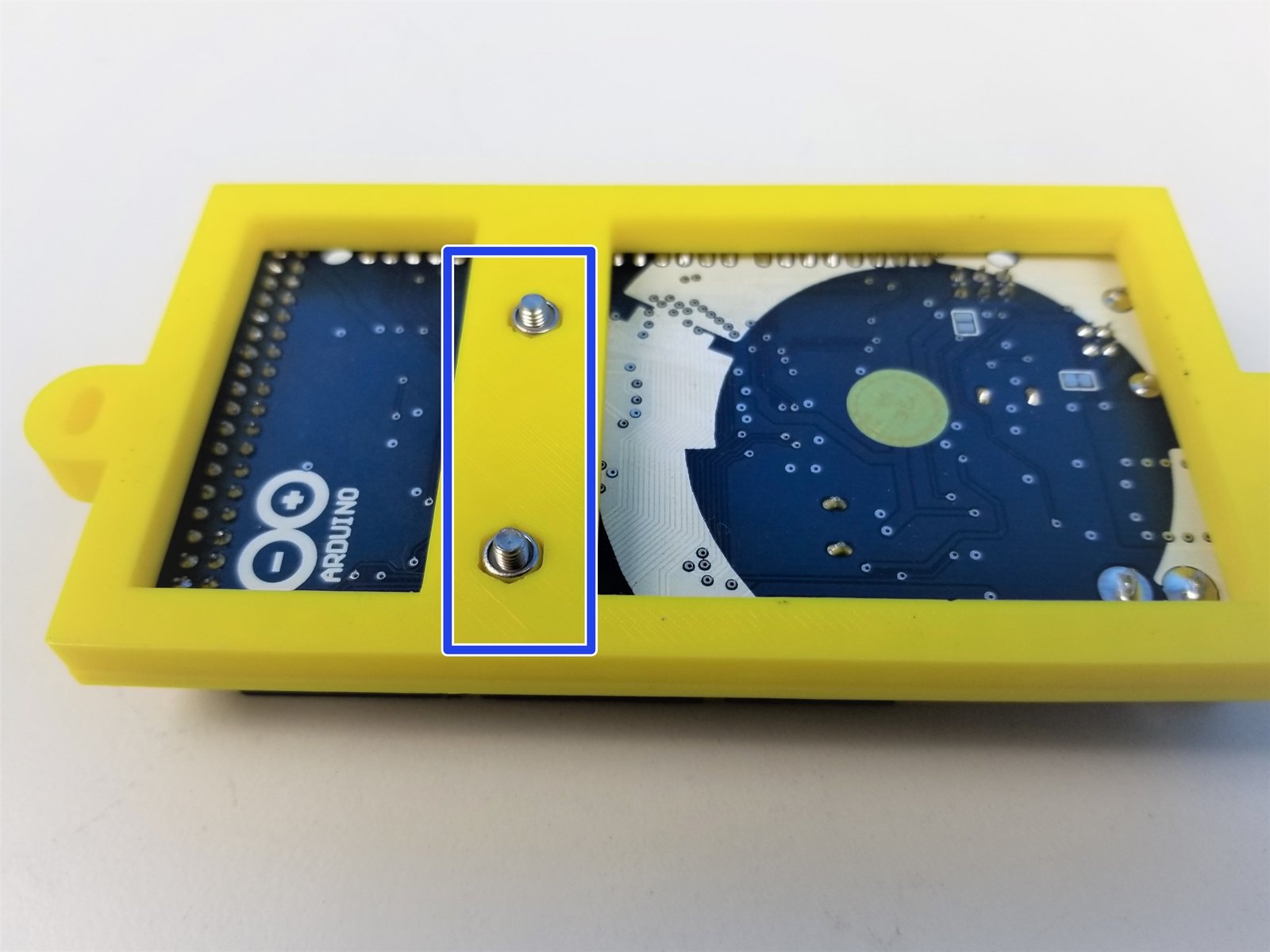
Step 21 Arduino Installation - Tray Preparation
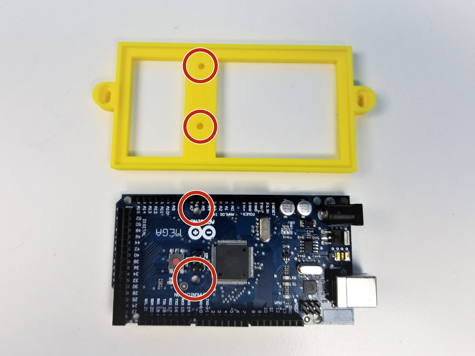
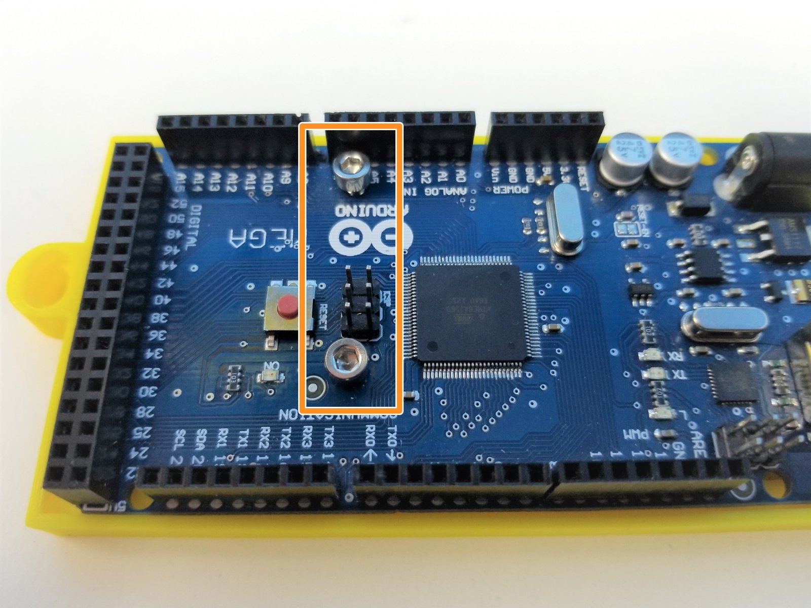
Click the large image to open full size.
Align the Holes on the Tray and the Arduino Mega
Use the M3x10mm Screws and M3 Nylock Nuts to secure the Arduino to the Tray
- Warning:
Make sure to tighten the screws just enough to hold them together, No more, since over-tightening the screws can damage the board.
Step 22 Arduino Installation - Arduino Mega Shield
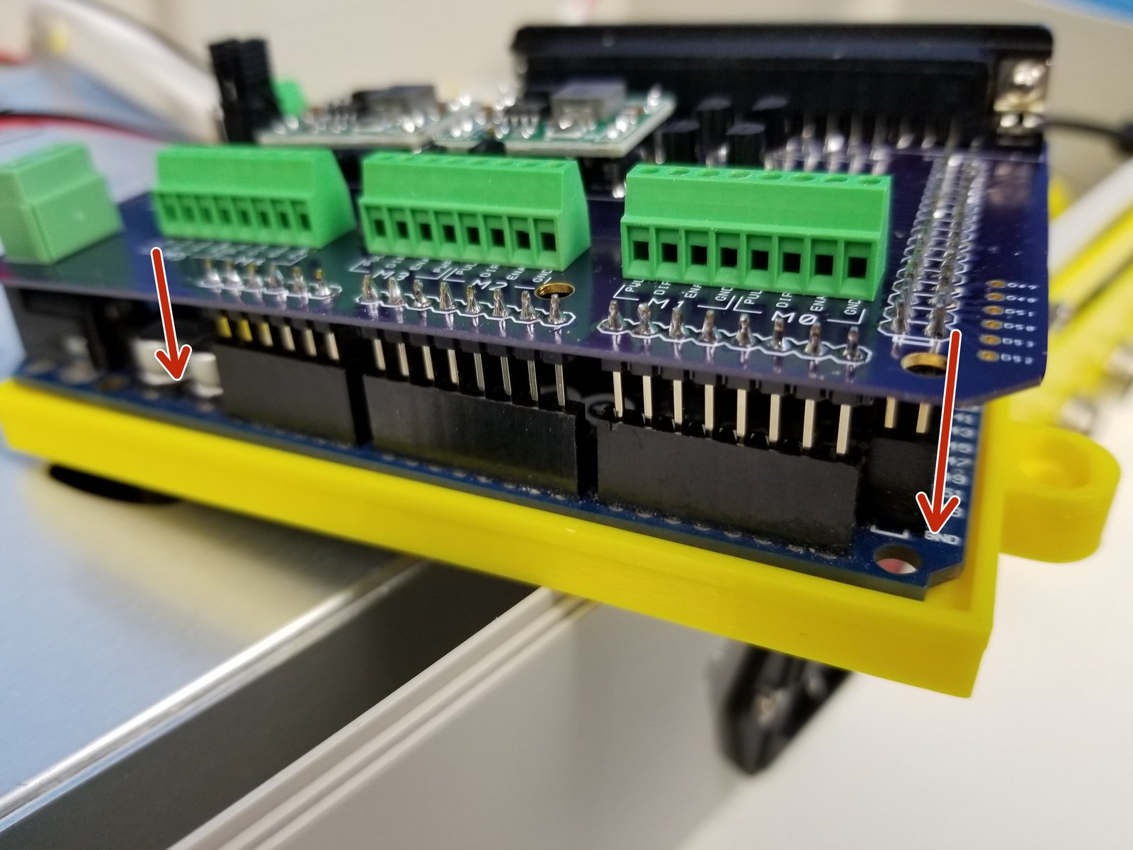
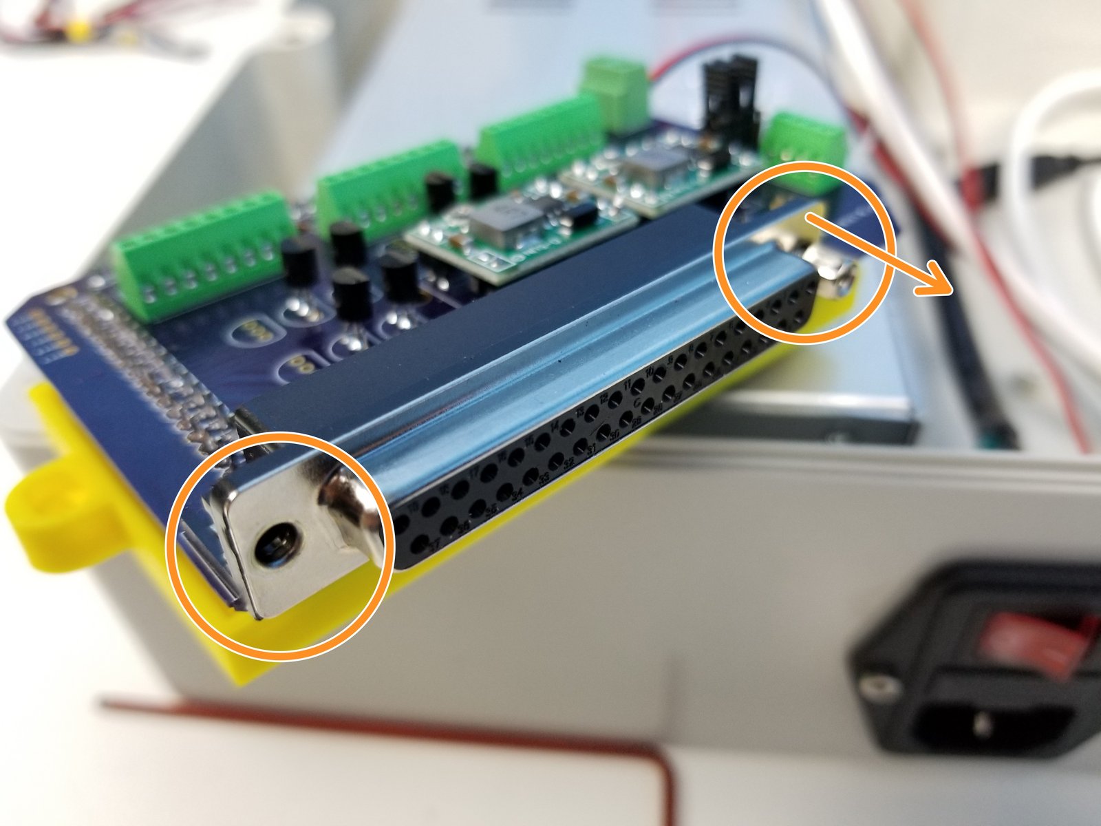
Click the large image to open full size.
Insert the Mega Shield to the Arduino Mega
- Warning:
Make sure you have set the voltage regulator in Step 11 before going forward
Remove the hex head screw from the Right Angle D-Sub Connector
Step 23 Arduino Installation - Motor Signal Cables
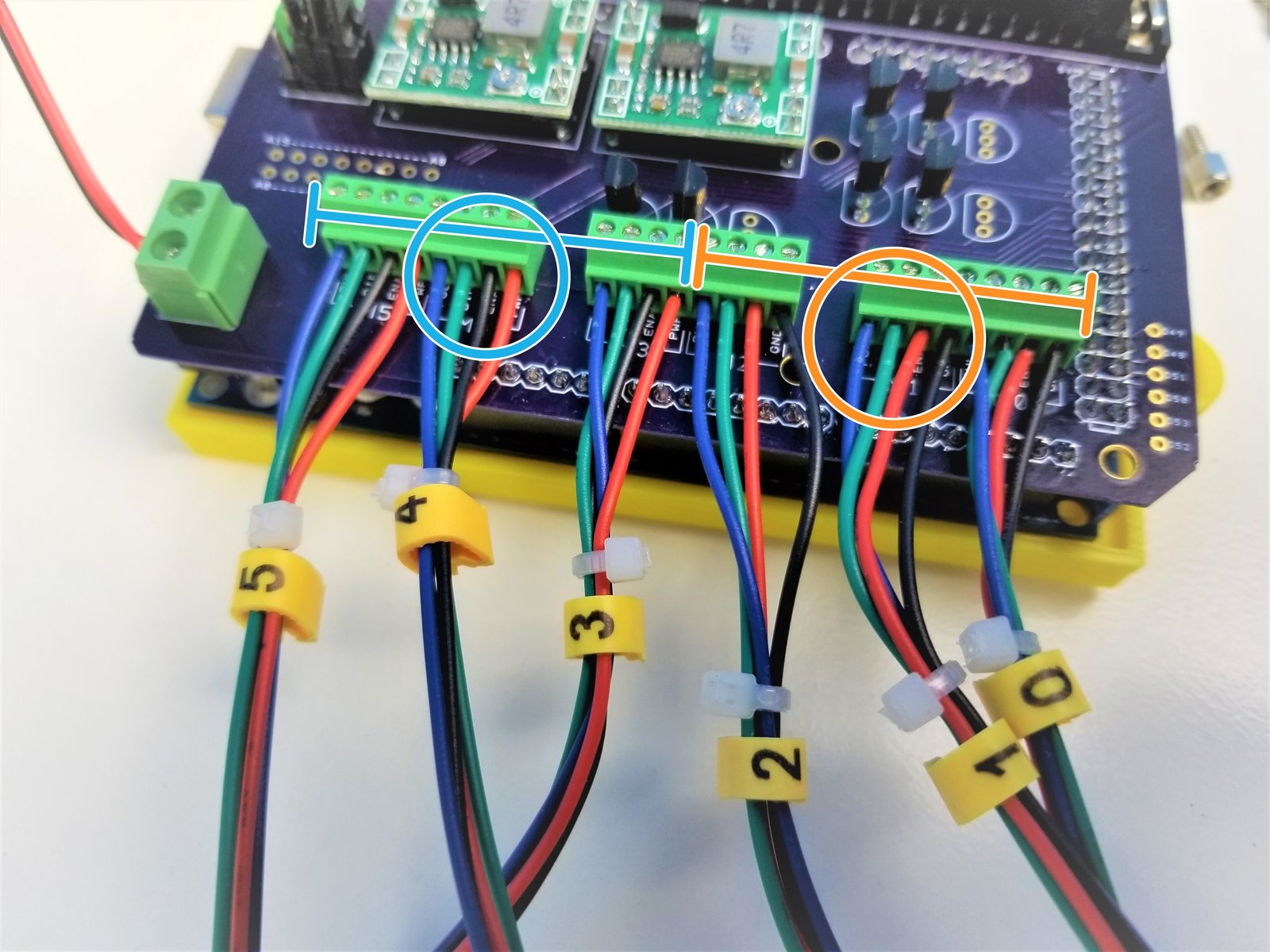
Click the large image to open full size.
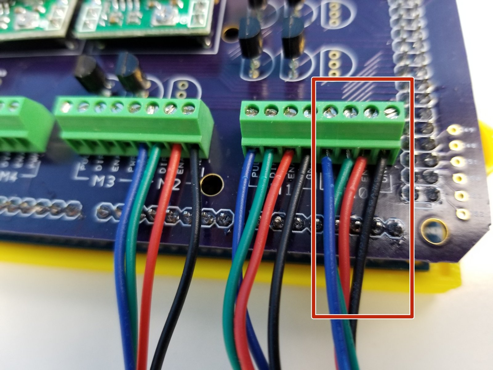
Start with Motor 0 signal cable to the Right most connector labelled "M0"
M0, M1 and M2 follows the same color pattern
- Note:
from the right, Black, Red, Green, Blue
M3, M4, M5 follows a different color pattern from M0-M2,
- Note:
from the right, Red, Black, Green, Blue
Step 24 Arduino Installation - Tool and USB
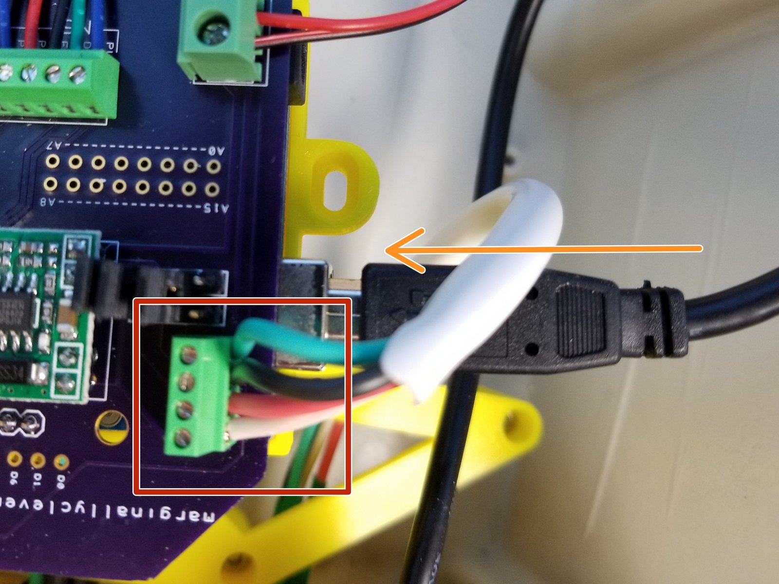
Click the large image to open full size.
Insert the "TOOL" Cable in the specific order:
- Note:
from the top, Green, Black, Red, White
Insert the USB Extension Cable in the Arduino
Step 25 Arduino Installation - Tray Mounting
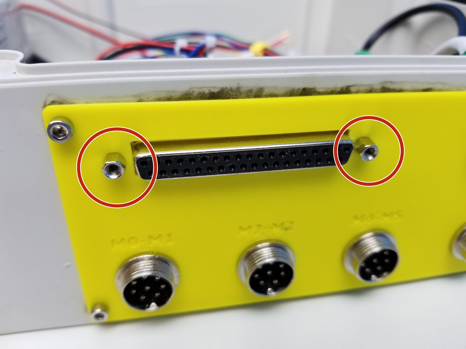
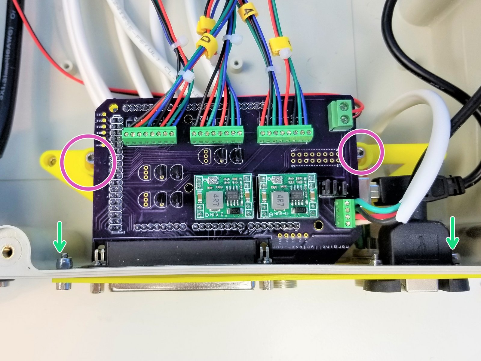
Click the large image to open full size.
Secure the Right Angle D-Sub Connector to the Case Wall Adapter slot using the Hex Head Screws
Align the Tray to the Standoff and secure it using the M3x10mm Screws
Once everything is aligned, secure this alignment by tightening the screw and the nut on the Case Wall Adapter
Step 26 Stepper Drivers Installation - Parts
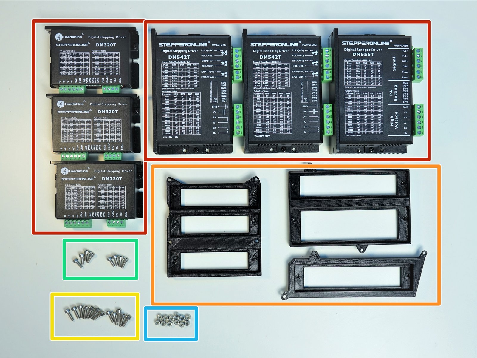
Click the large image to open full size.
- Note:
Prepare the following components:
Stepper Drivers [DM320T & DM542T & DM556T]
[3D] Stepper Driver Adapters
M3x10mm Screws (x12)
M3x8mm Screws (x9)
M3 Nylock Nuts (x12)
Step 27 Stepper Drivers Installation - DM320T
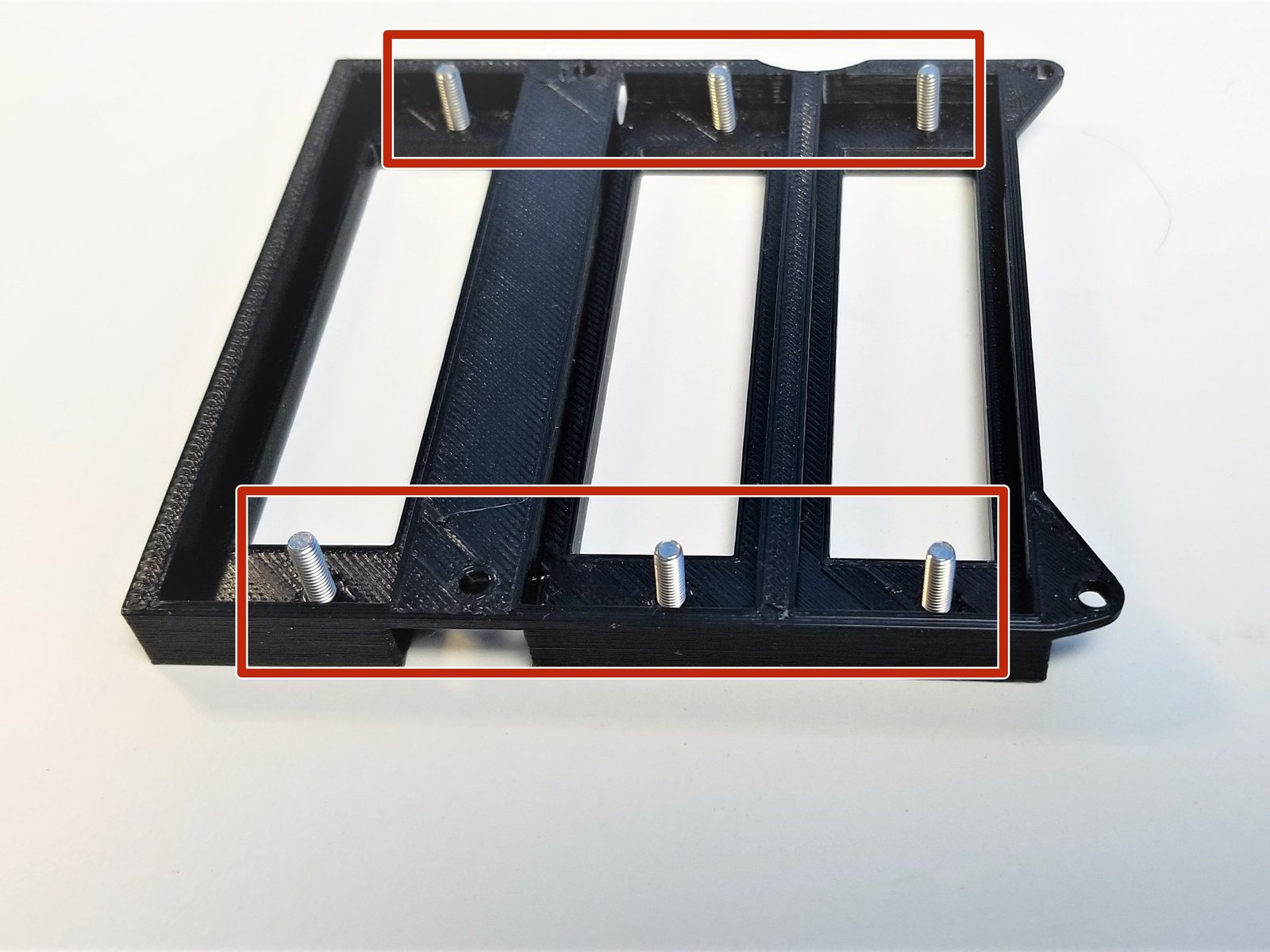
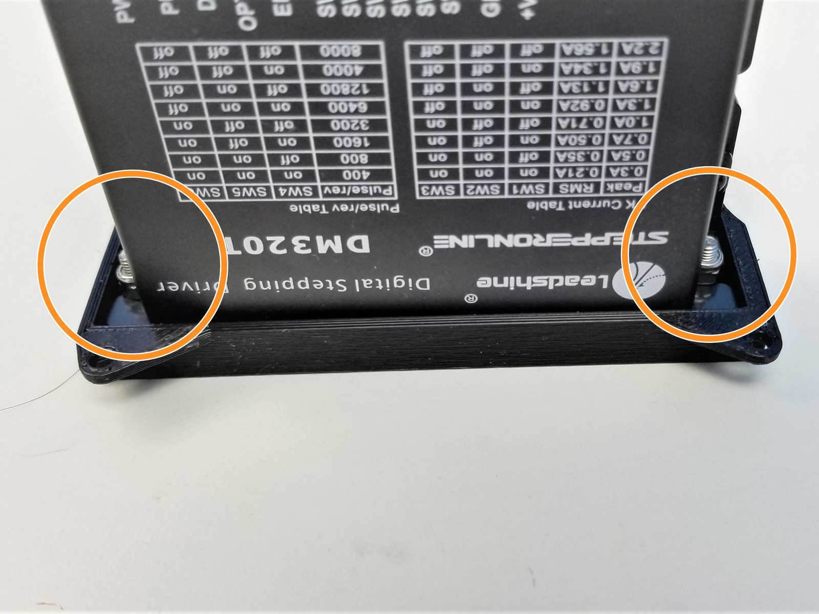
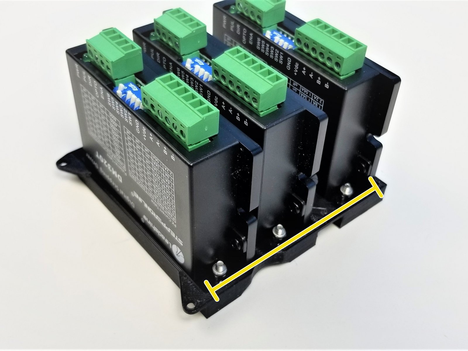
Click the large image to open full size.
Starting with the Smaller "DM320T" Drivers, screw in M3x10mm Screws in the Adapter with 3 small slots
One driver at a time, secure the drivers to the adapter using M3 Nylock Nuts, use Needle Nose Plier to hold the nuts.
Repeat the process for the rest of the DM320T Drivers
Step 28 Stepper Drivers Installation - DM542T and DM556T
Click the large image to open full size.
- Note:
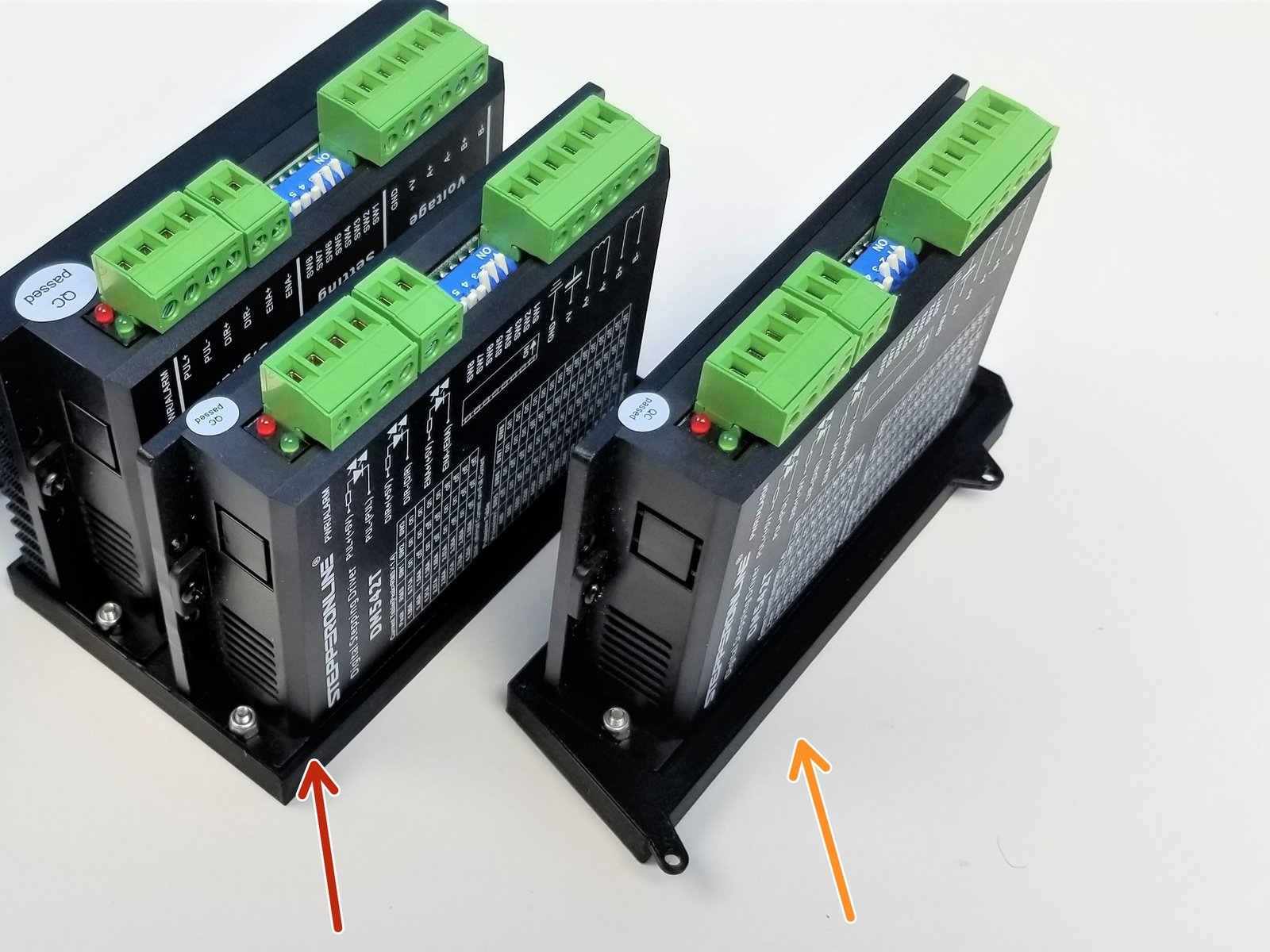
There are two DM542T Drivers and one DM556T Driver, DM556T Driver is the one with a big Heat Sink in the back
Repeat the same process as previous step:
Adapter with 2 Slots, fits each DM542T and DM556T
Adapter with a single slot fits one DM542T Driver
Step 29 Stepper Drivers Installation - Driver Adapters Mounting
Click the large image to open full size.
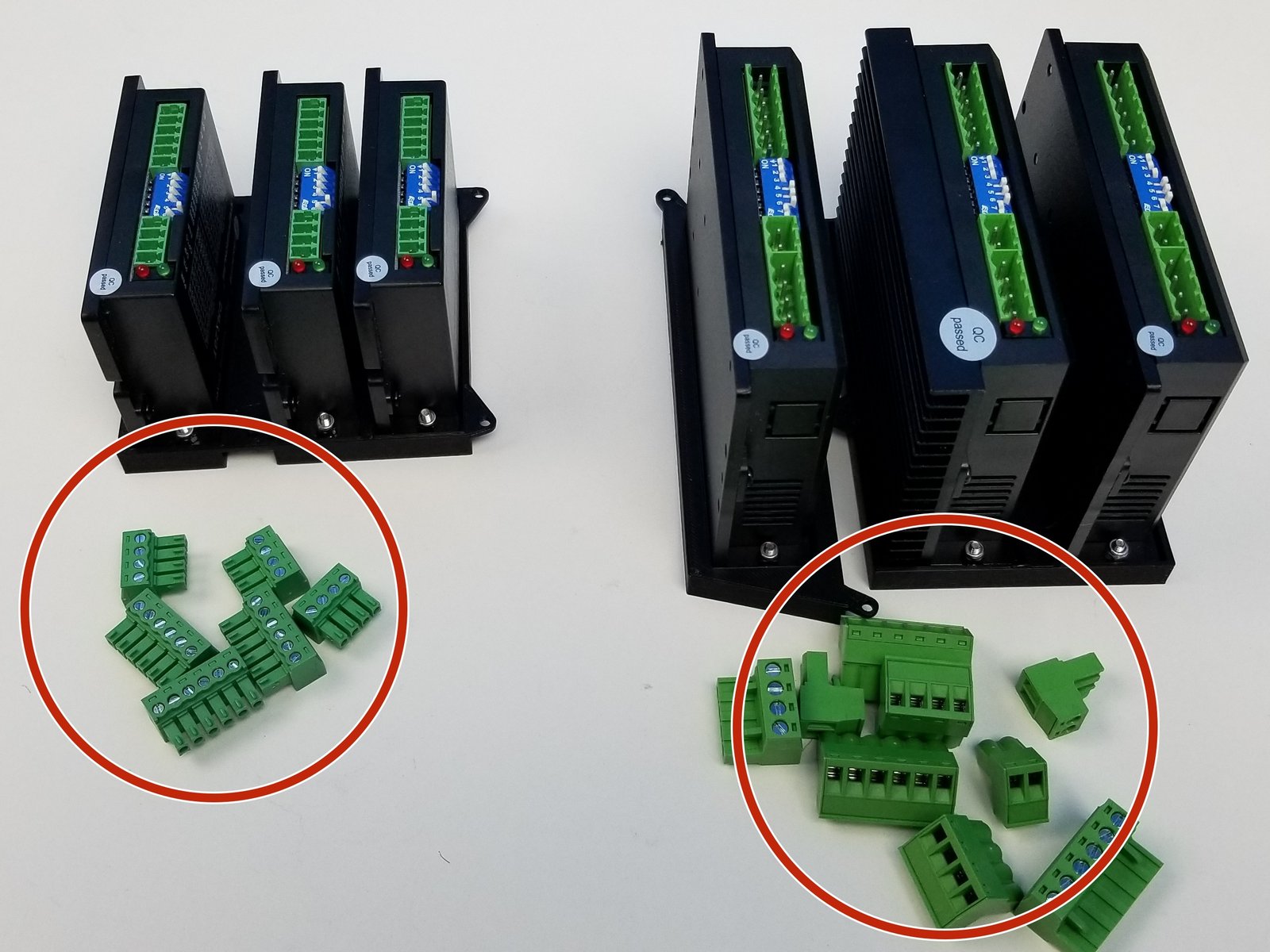
Pull all the Screw Terminal Blocks off from the Drivers
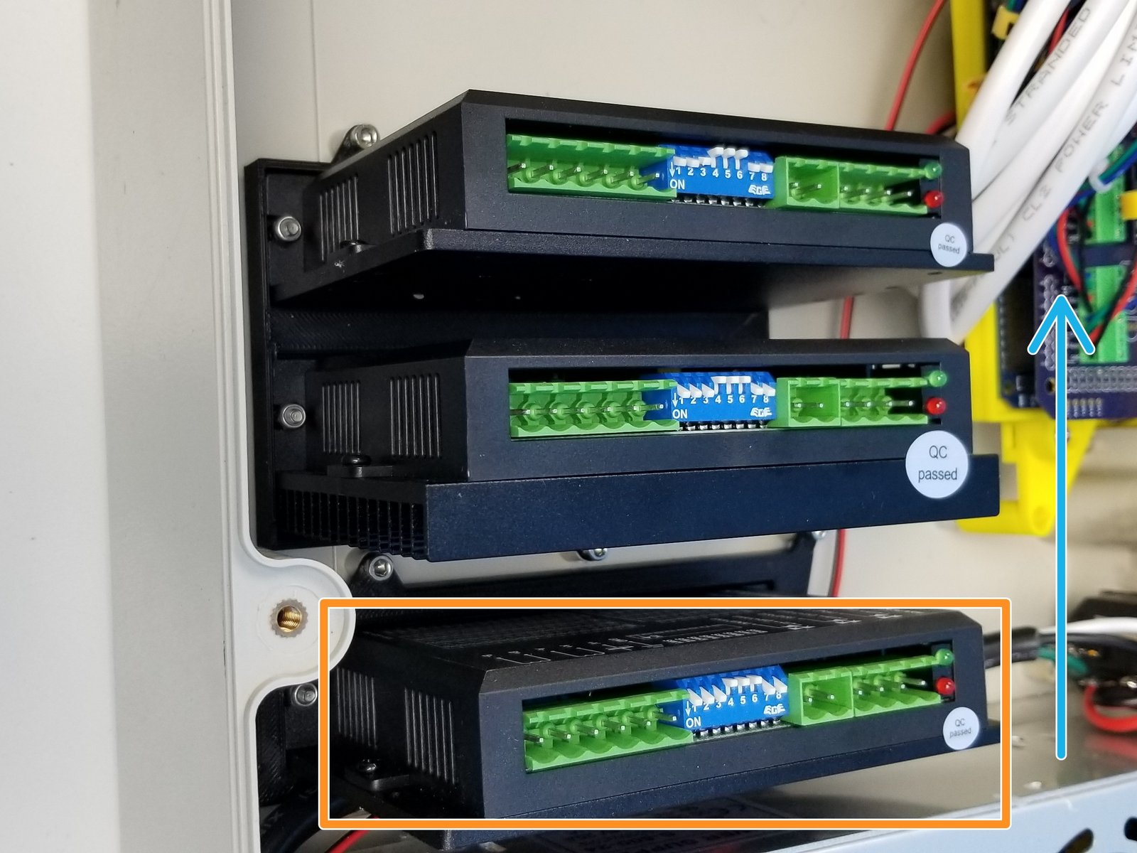
Starting with a single DM542T Driver Adapter, secure each drivers to the Case
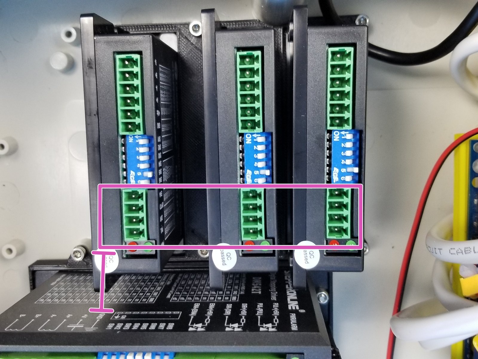
Make sure the adapters are aligned as shown in the picture, Label on the DM542T and DM556T Drivers are facing away from the PSU
For DM320T Drivers, 4 pin side is closer to the Label of DM542T Driver
Step 30 Stepper Drivers Installation - Driver Switch Modes
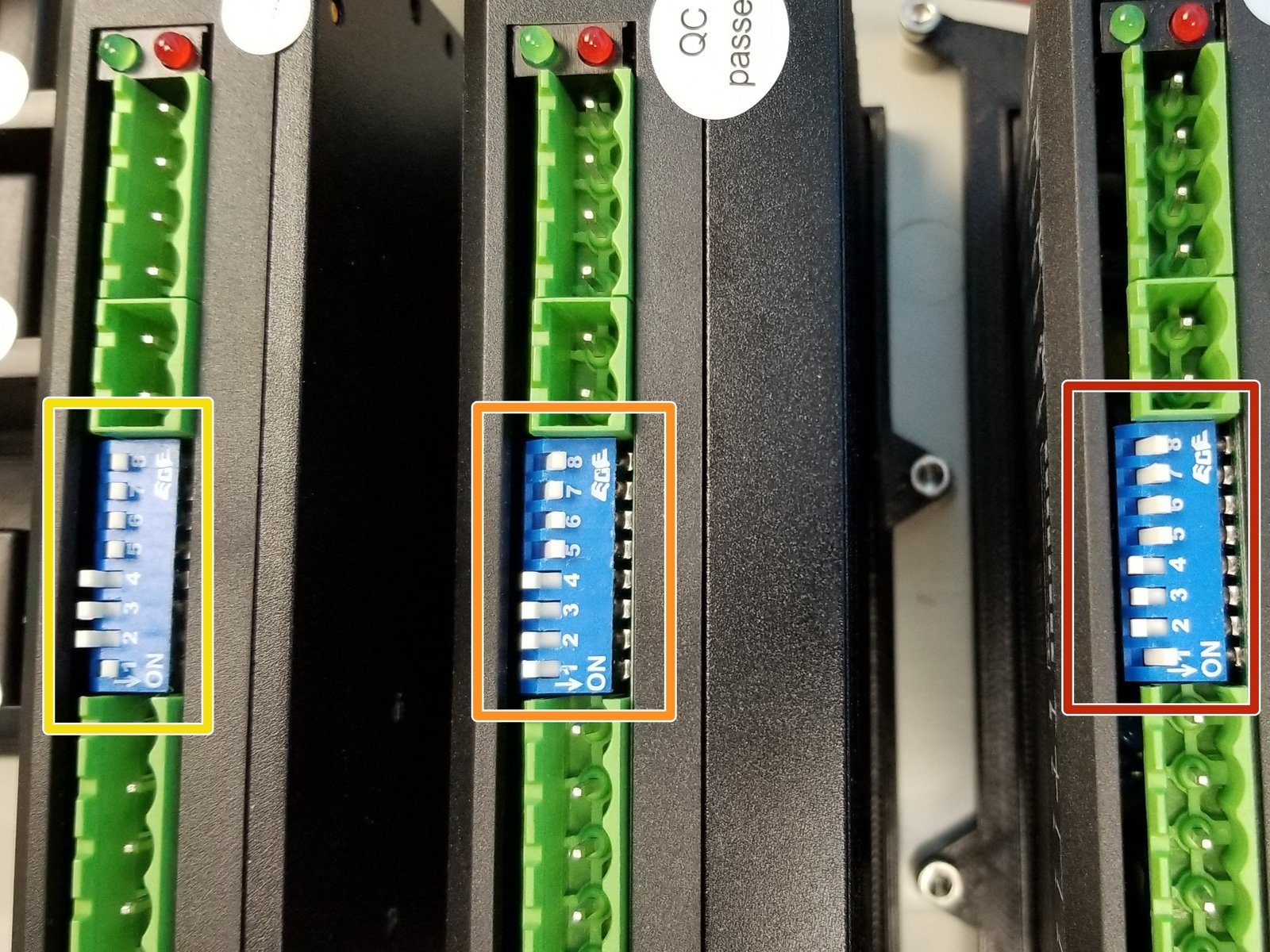
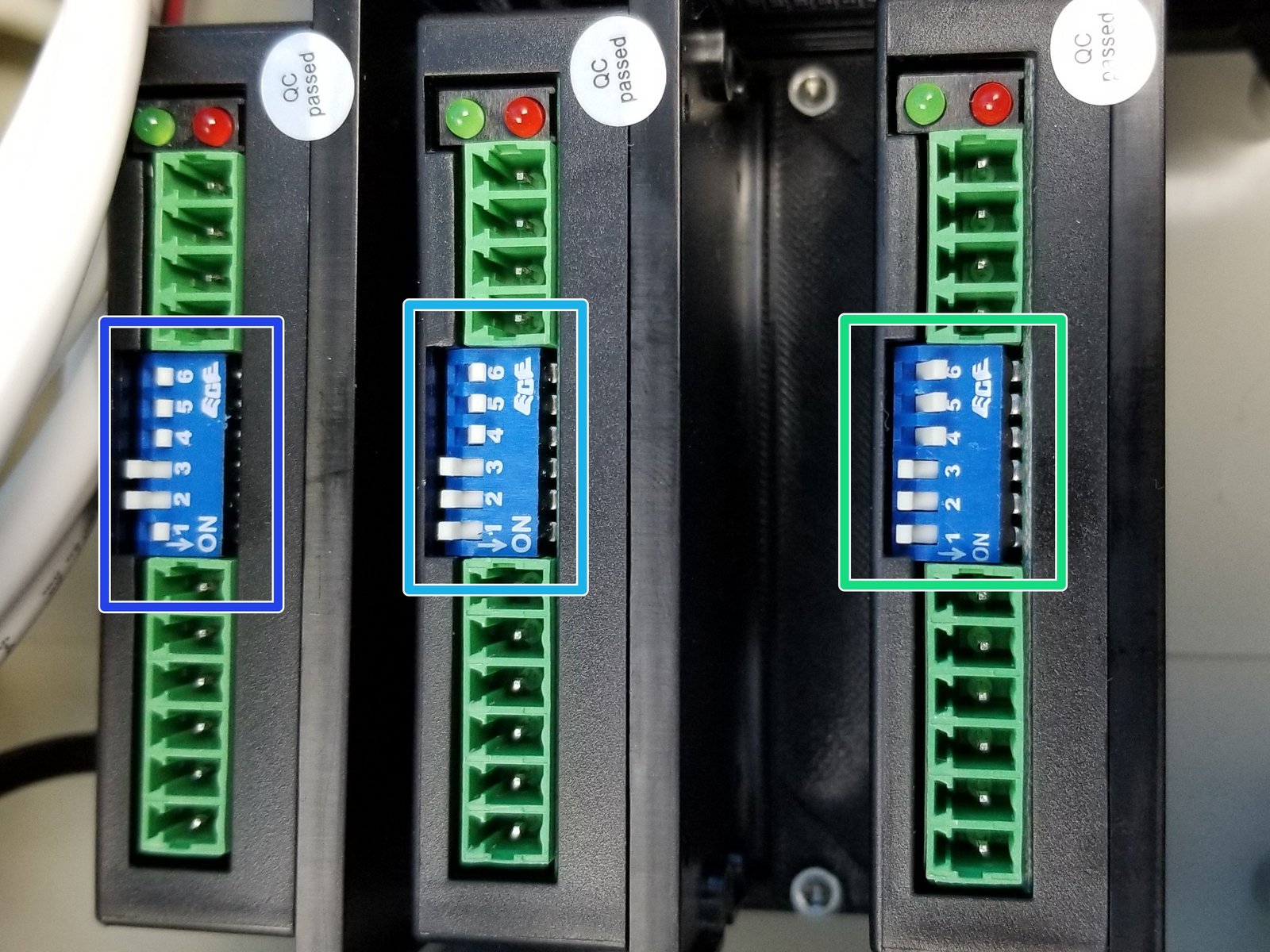
Click the large image to open full size.
- Note:
Set the switch to the following mode, it'll follow the Binary scheme, 1 = On, 0 = Off, starting from switch 1 in ascending order
DM542T -> 10001111
DM556T -> 00001111
DM542T -> 10001111
DM320T-Right -> 000111
DM320T-Middle -> 000111
DM320T- Left -> 100111
Step 31 Final Cable Assembly - Parts
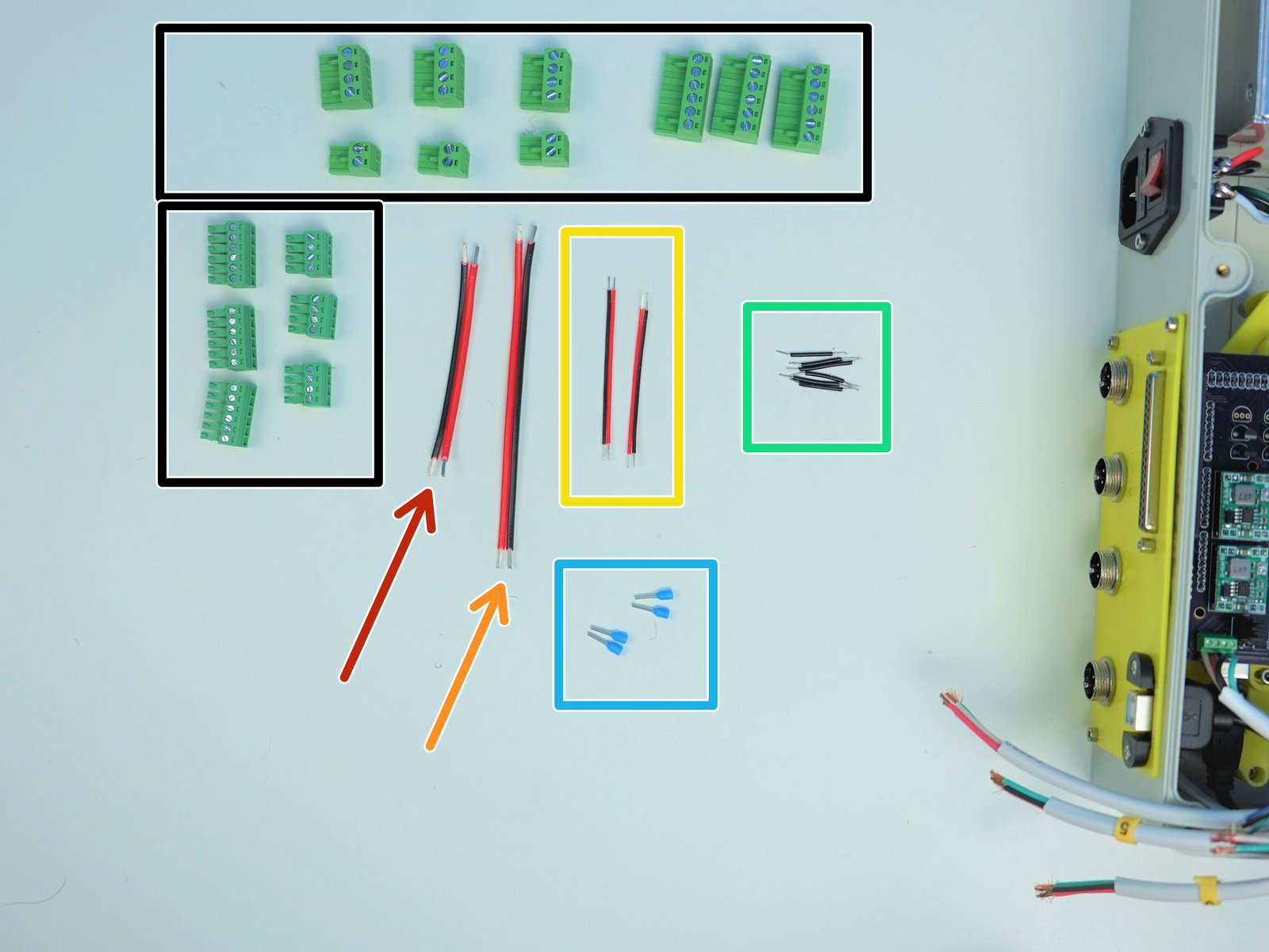
Click the large image to open full size.
- Note:
Prepare the following components:
Screw Terminal Blocks from the Drivers
2-pin Power Wires 18AWG 90mm
2 pin Power Wires 18AWG 130mm
2 pin Power Wires 22AWG 65mm (x2)
22 AWG solid Wires Black 30mm (x6)
[Opt] - Ferrule Crimp Pins (x4)
Step 32 Final Cable Assembly - DM542T & DM556T Signal Wiring
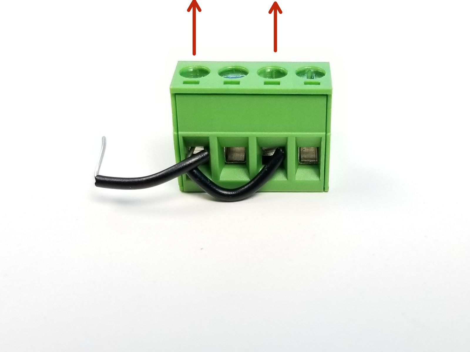
Click the large image to open full size.
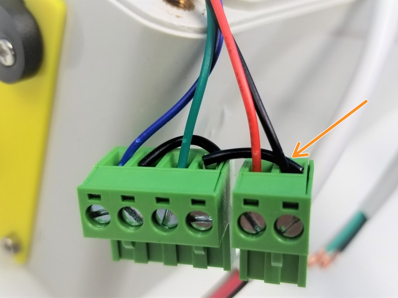
Grab one of the Bigger Driver's 4-pin Screw Terminal and wire it as shown in the first picture, Screw Head is pointing UP
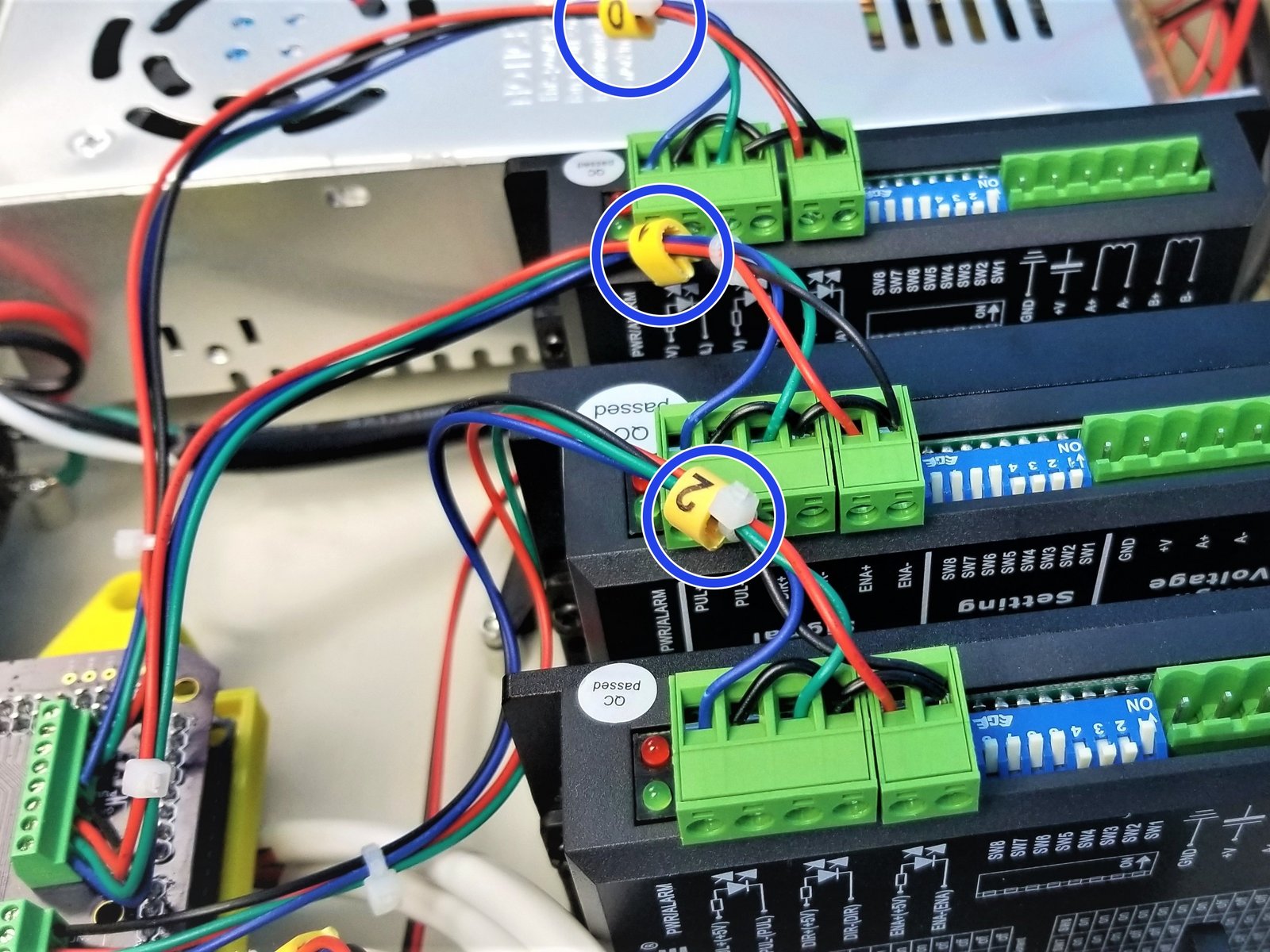
Starting with M0 Cables that's already attached to Arduino Mega Shield, secure the wire as shown in the second picture.
- Warning:
notice there are 2 black solid wires in the right most pin of the 2-pin connector
Repeat the same process for the M1 and M2 Drivers, and plug them as shown in the third picture.
Step 33 Final Cable Assembly - DM320T Signal Wiring
Click the large image to open full size.
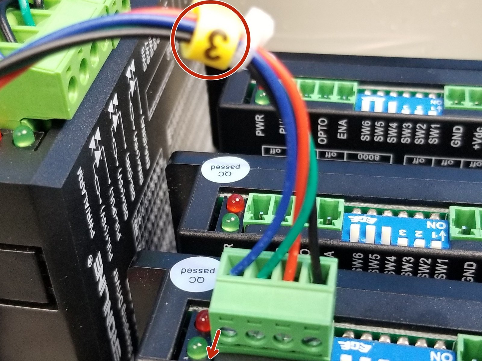
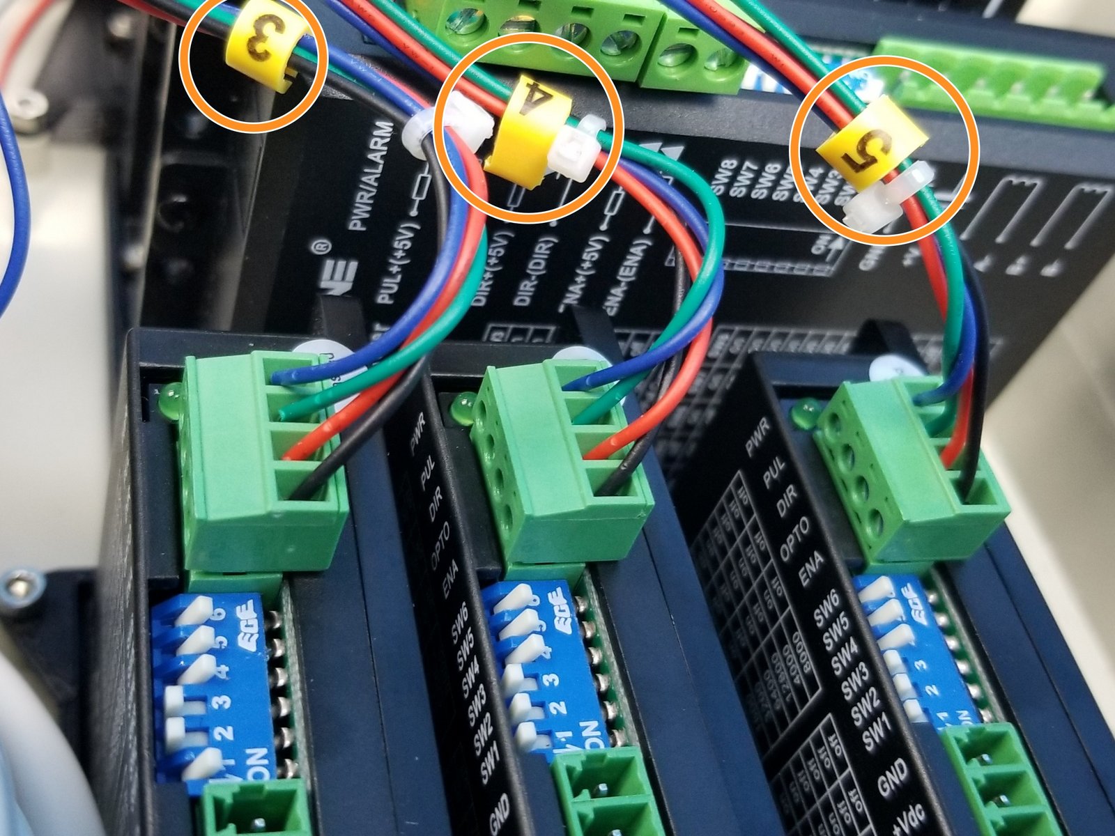
Starting with the M3 signal cable, attach them and plug them in the corresponding driver as shown in the first picture,
Repeat the process for M4 and M5 drivers, notice the labels
Step 34 Final Cable Assembly - DM542T & DM556T Power Wiring
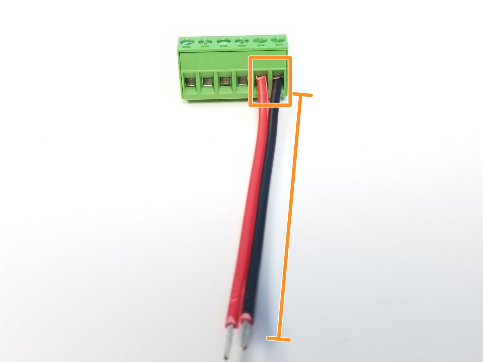
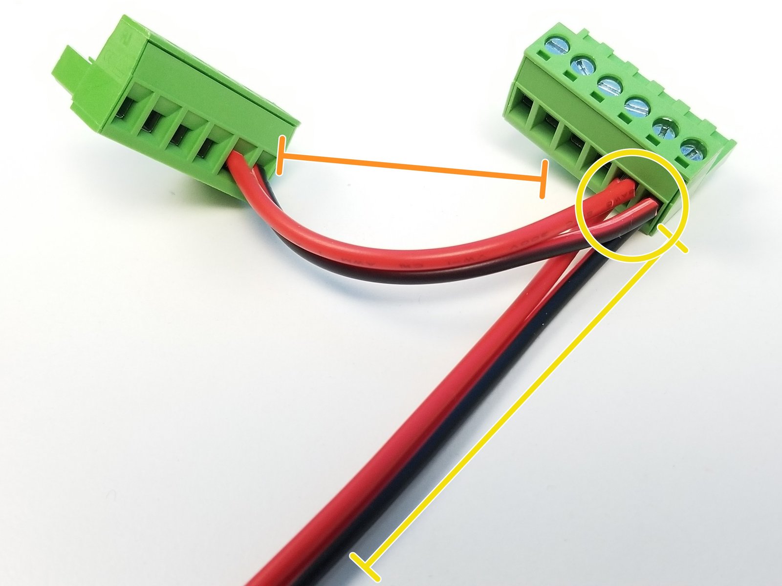
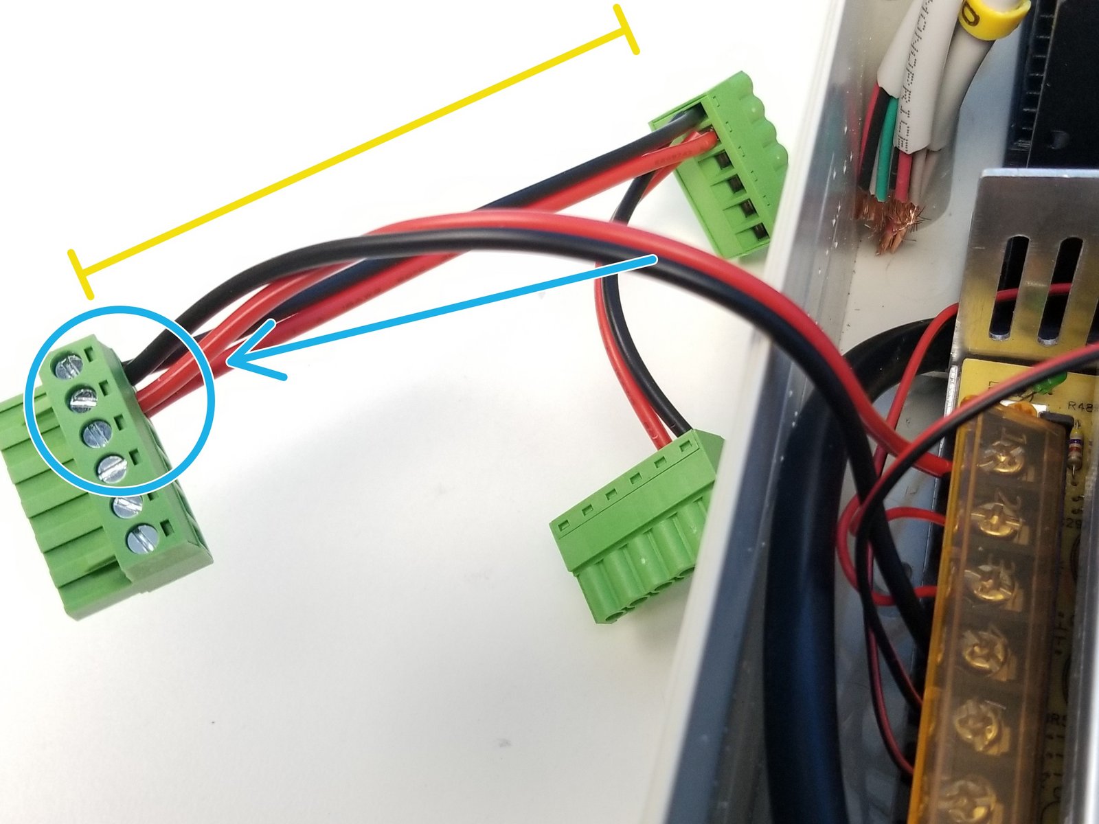
Click the large image to open full size.
Use the shorter 18AWG 2-pin power cable and attach it to big 6-pin screw terminal
Attach the other end of the shorter 18AWG cable and one end of the longer 18AWG to another 6-pin screw terminal
Now repeat the second step with the longer 18AWG cable and the 18AWG cable that's already in the PSU with the last 6-pin screw terminal
Step 35 Final Cable Assembly - M0-2 Power Cable
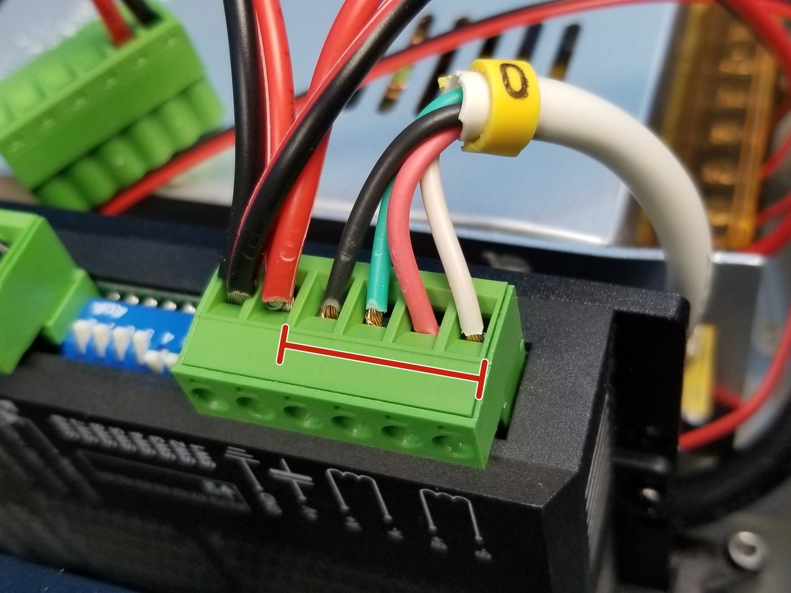
Click the large image to open full size.
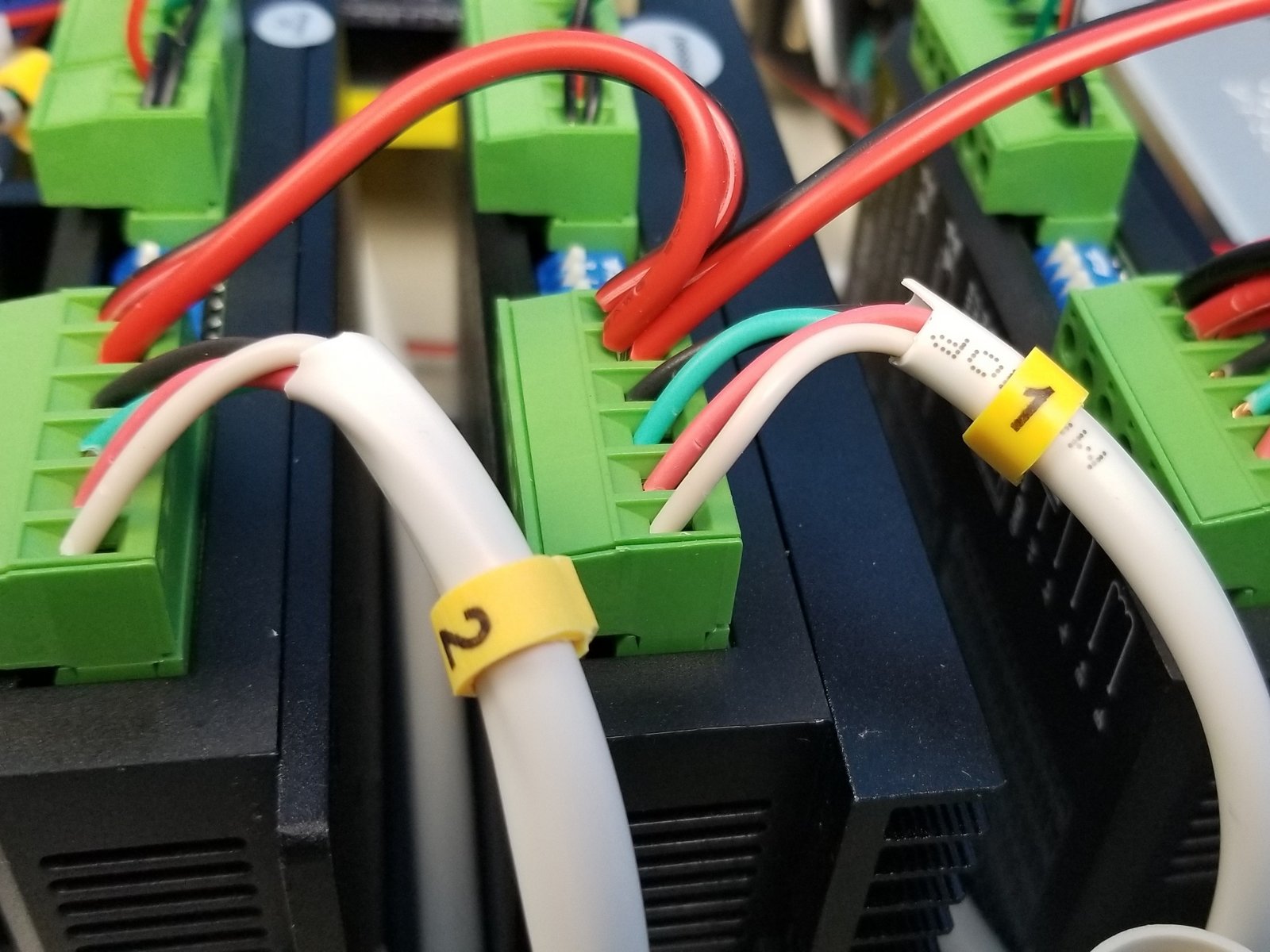
Start with M0 cables from the GX16 Aviation Plug and the screw terminal that's directly connected to PSU.
- Note:
Start with Black, Green, Red, White
Repeat the same process for M1 and M2 as shown in the second picture.
Step 36 Final Cable Assembly - DM320T Power Wiring
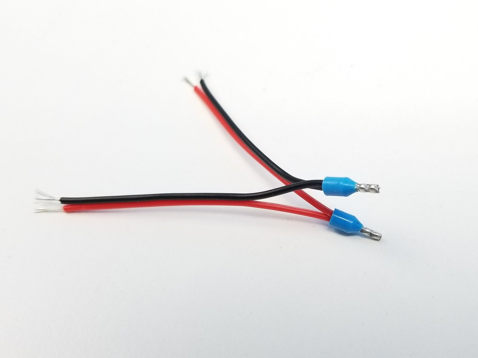
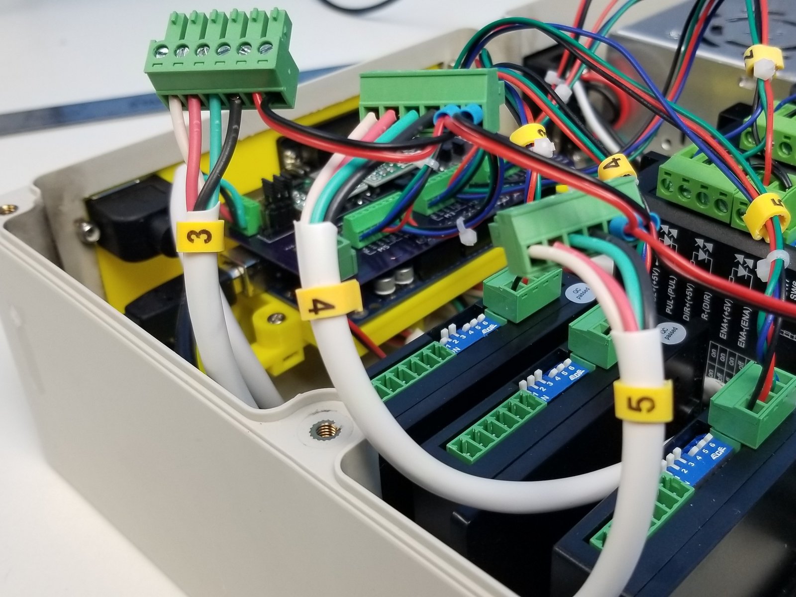
Click the large image to open full size.
- Note:
Optional Step:
Use the Ferrule Crimp Pins to connect 22AWG power wires as shown in the first picture, do this for cable from PSU as well.
The same color code as bigger drivers applies to DM320T, just repeat step 30 with M3-5 Motor Wires
Step 37 FINISHED!
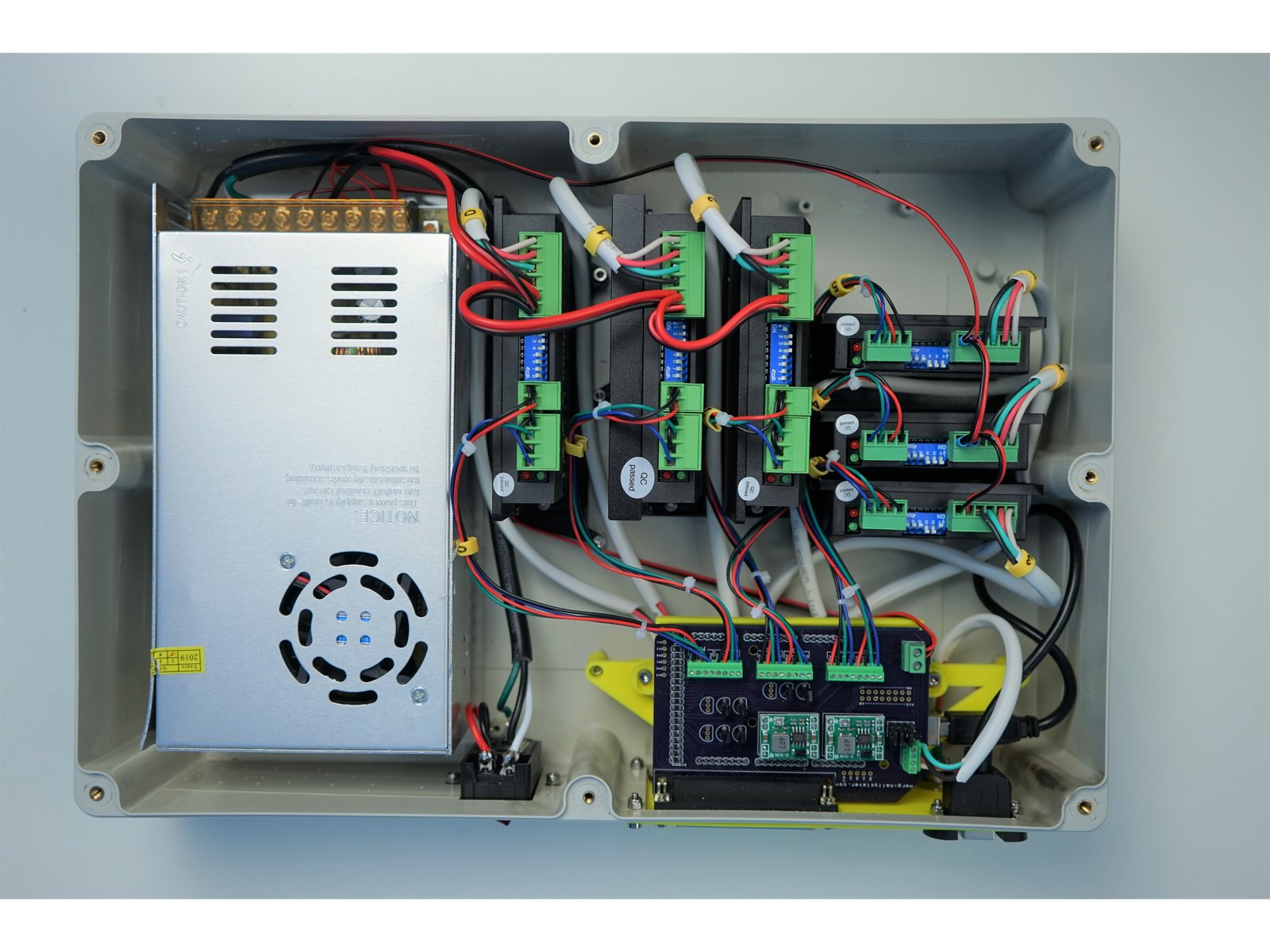
Click the large image to open full size.
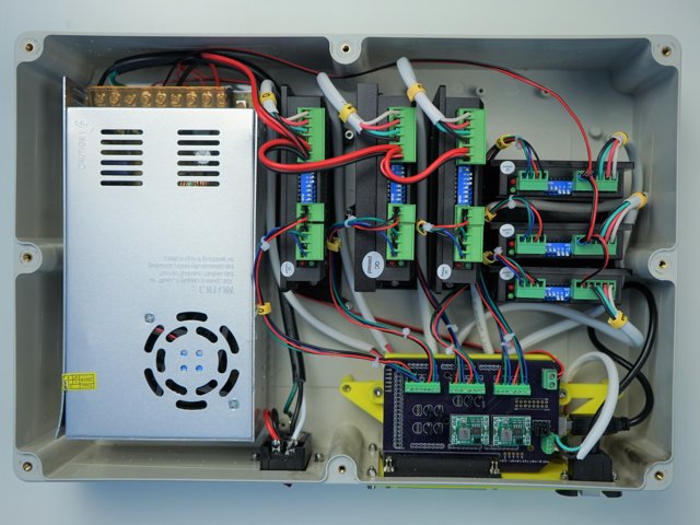
Congratulation! you've successfully finished assembling the Electronic Case! Go You!