Makelangelo 6
Makelangelo 6 construction
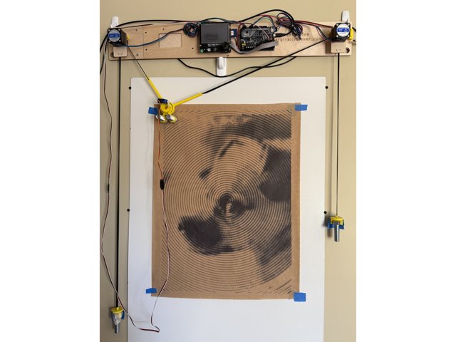
This guide will explain how to assemble the main body of the Makelangelo 6, including motors, electronics, and power supply. It does not include after-delivery steps like mounting on a wall, assembling the pen holder, or the counterweights.
Tools
- M3 wrench/nut driver
- M3 alan key
Step 1 Assemble the motor mounts
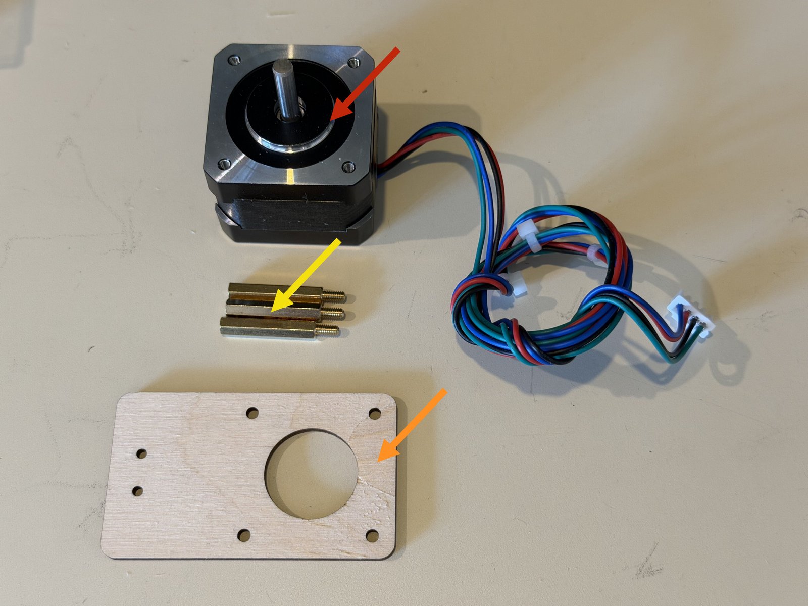
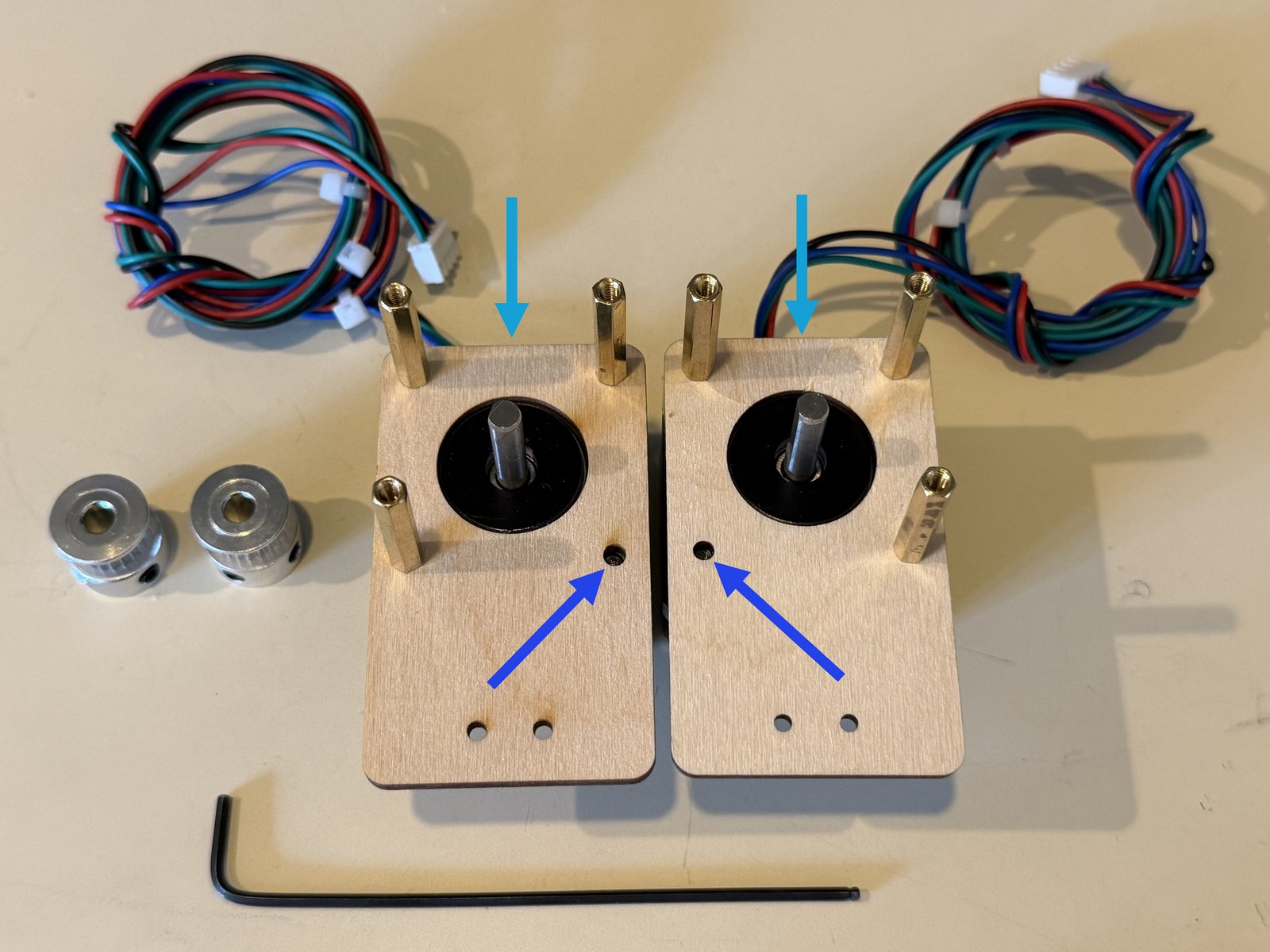
Click the large image to open full size.
This task is done twice, one a mirror of the other.
For each half, locate one motor;
One motor mount plate;
and three brass M3x25 standoffs.
Fasten the brass standoffs through the motor mount plate and into the motor as shown.
Note the direction of the cable coming out of the motor.
Note the difference in the standoff positions.
Step 2 Attach the pulleys to each motor mount
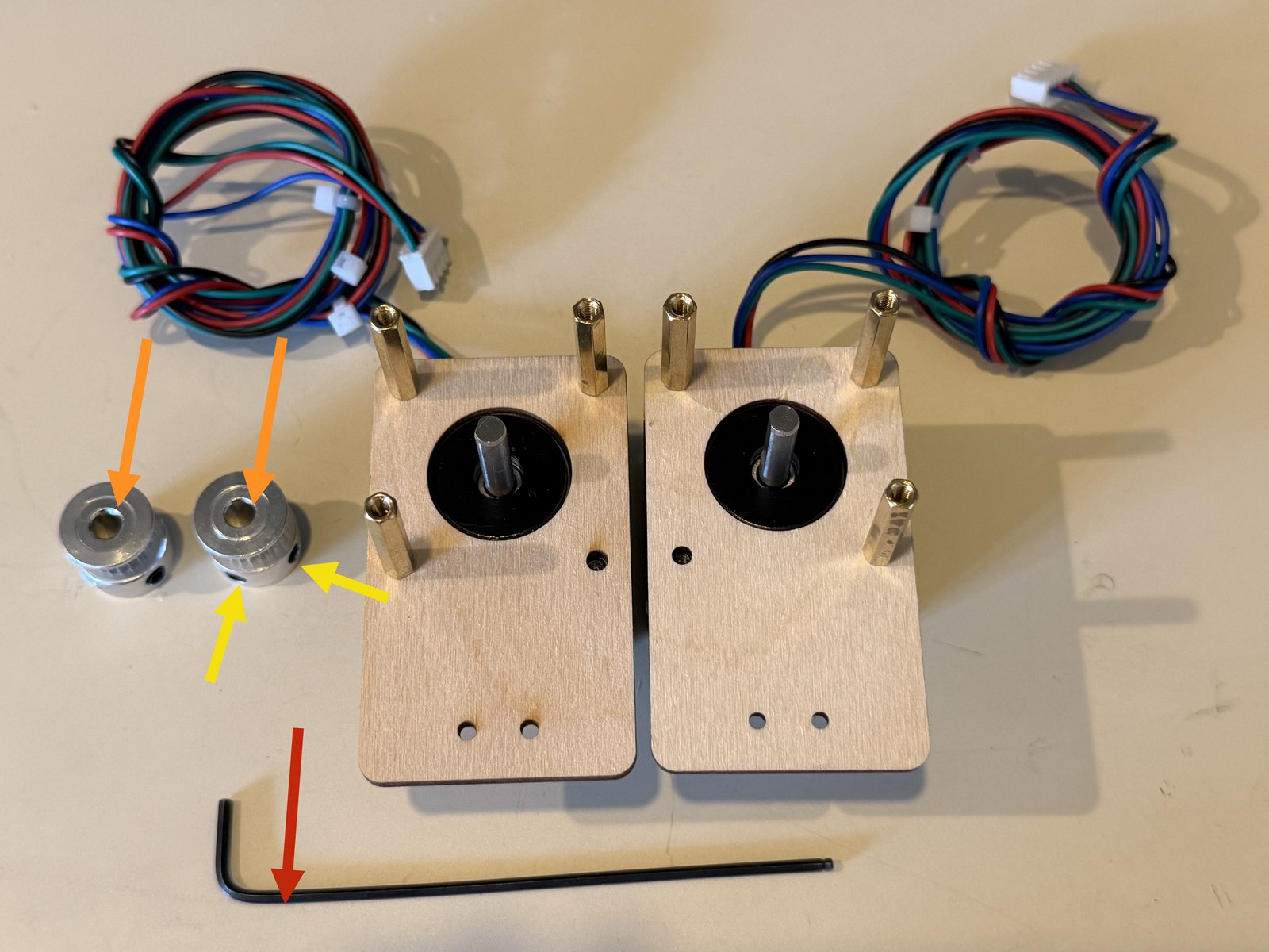
Click the large image to open full size.
Locate the M2 hex key.
Locate two M3x20x6 pulleys.
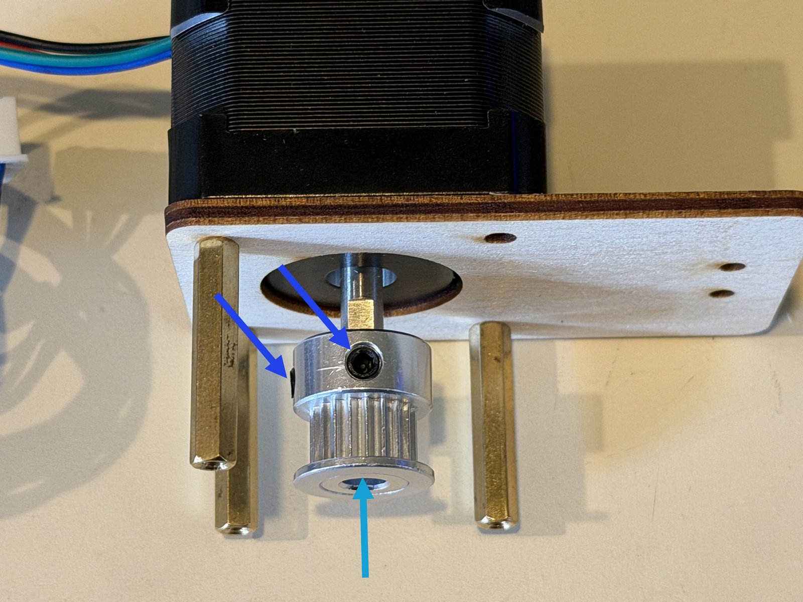
They should have two set screws each.
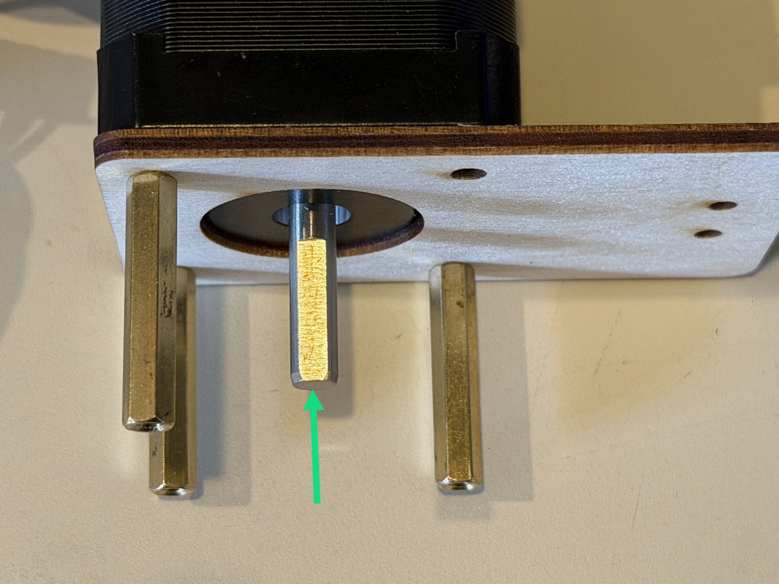
Turn one motor shaft to locate the flat side.
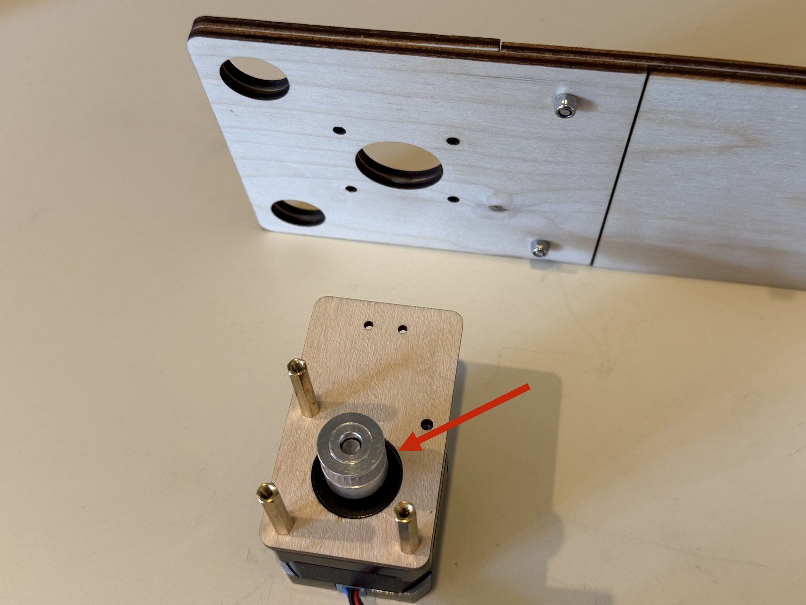
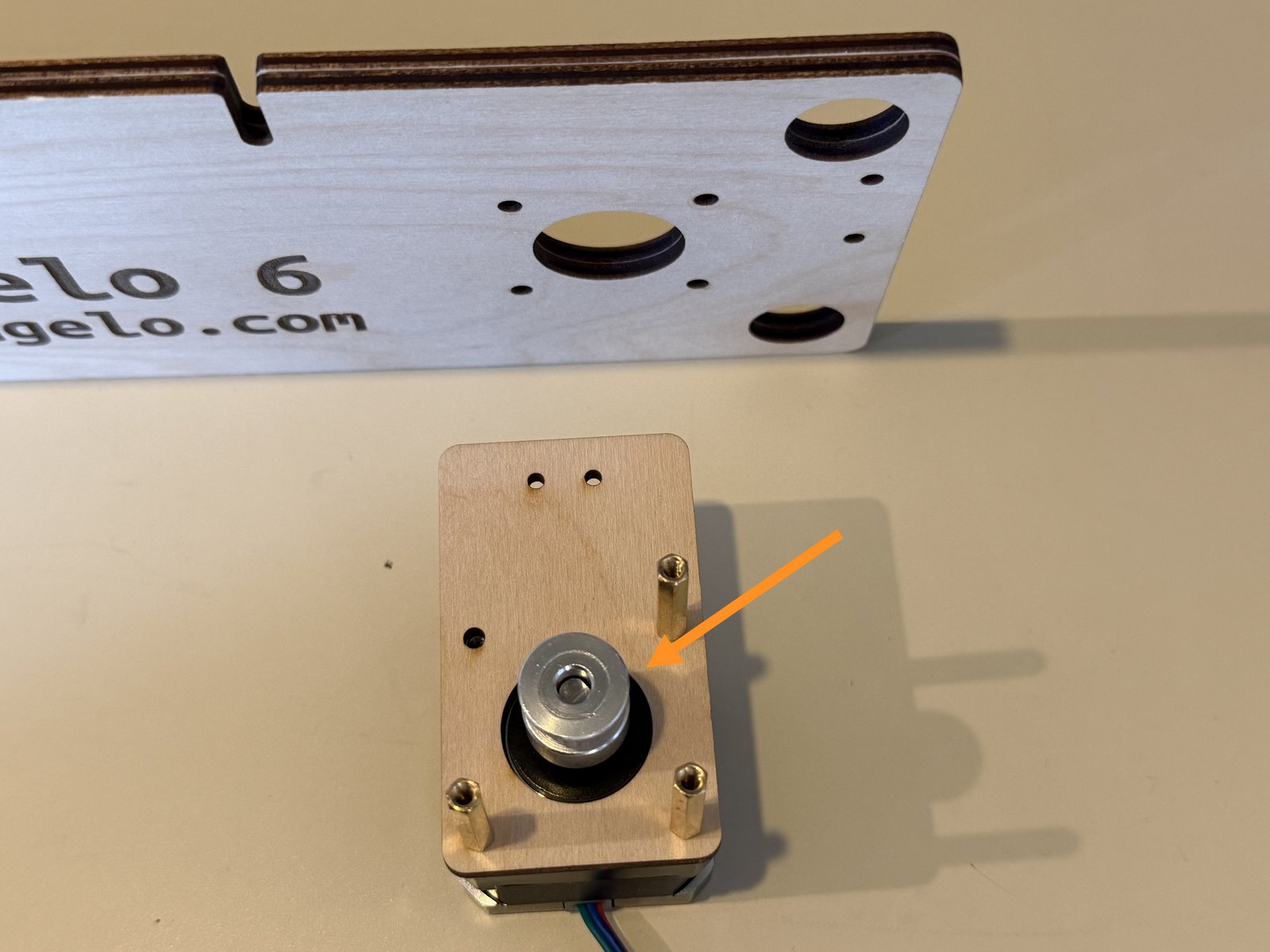
Put the pulley on the motor shaft with the set screw end towards the motor. The other end should be flush with the end of the standoffs.
Tighten the set screw on the flat side first, then the other.
- Note:
Repeat these steps for the other motor.
Step 3 Connect the back plate halves
Click the large image to open full size.
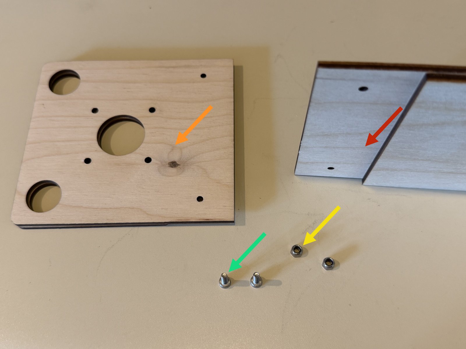
Locate the long back plate with the URL etched on the front. It should be made of two parts already be glued together.
Locate the short back plate. It should be made of two parts already be glued together.
Locate two M3x10 socket screws.
Locate two M3 nylock nuts.
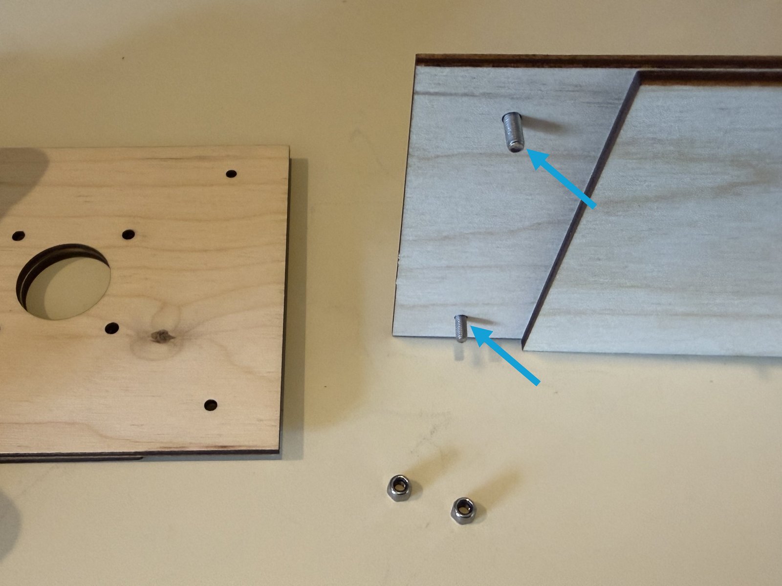
Push the screws through the long plate from back to front.
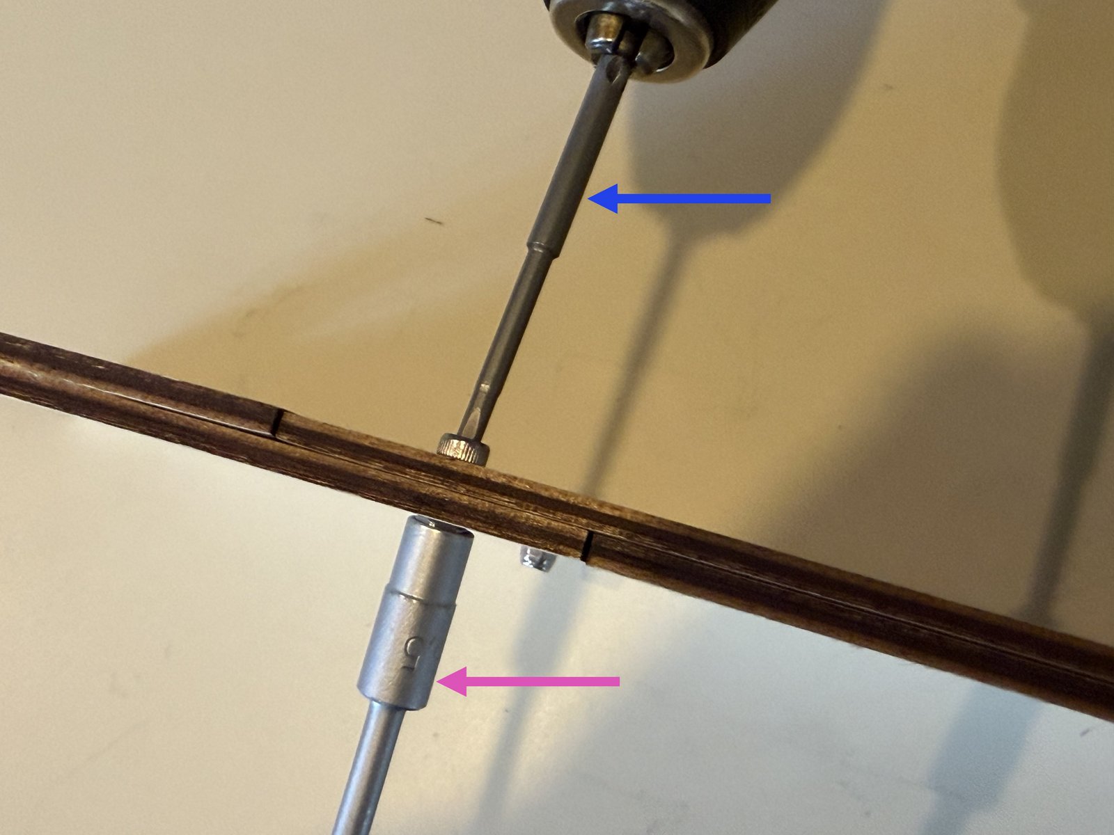
Using an M3 hex screwdriver (typically in a hand held drill)
and an M3 socket driver, tighten the M3 nylock onto the screw to hold the two plates together.
Step 4 Mount the motors to the back plate
Click the large image to open full size.
Place the left motor mount on the left. The standoffs tell you which motor mount is which.
Place the right motor mount on the right.
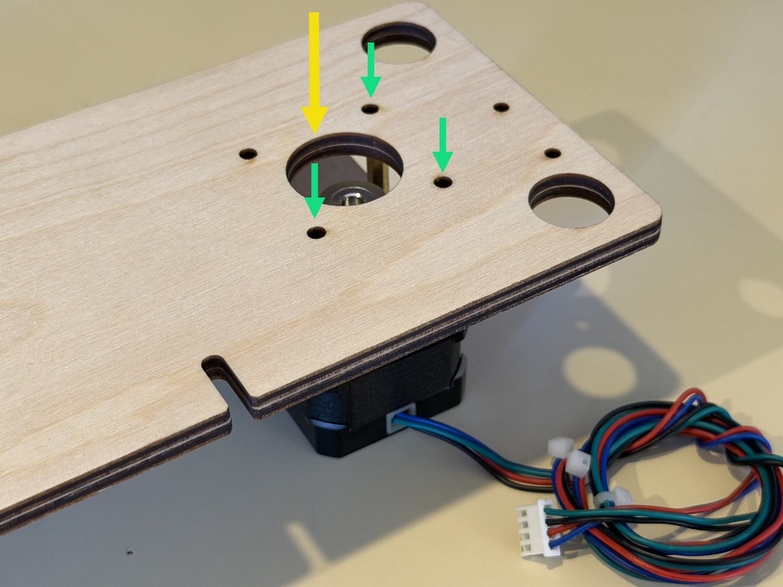
Place the back plate on top of the motor mounts.
Put one M3x10 socket screw through the holes provided into the three standoffs of each motor, for a total of six screws.
Step 5 More back plate screws
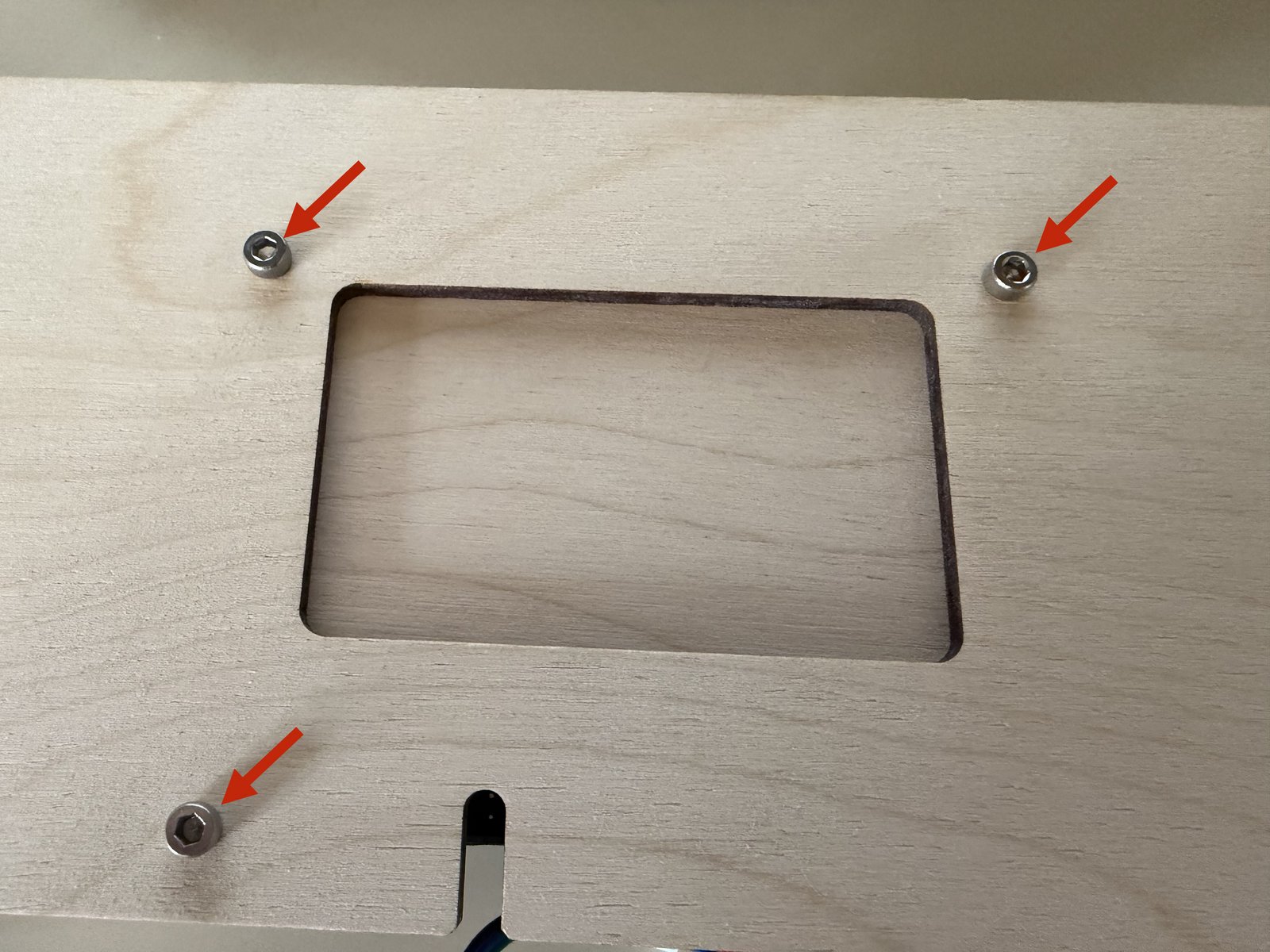
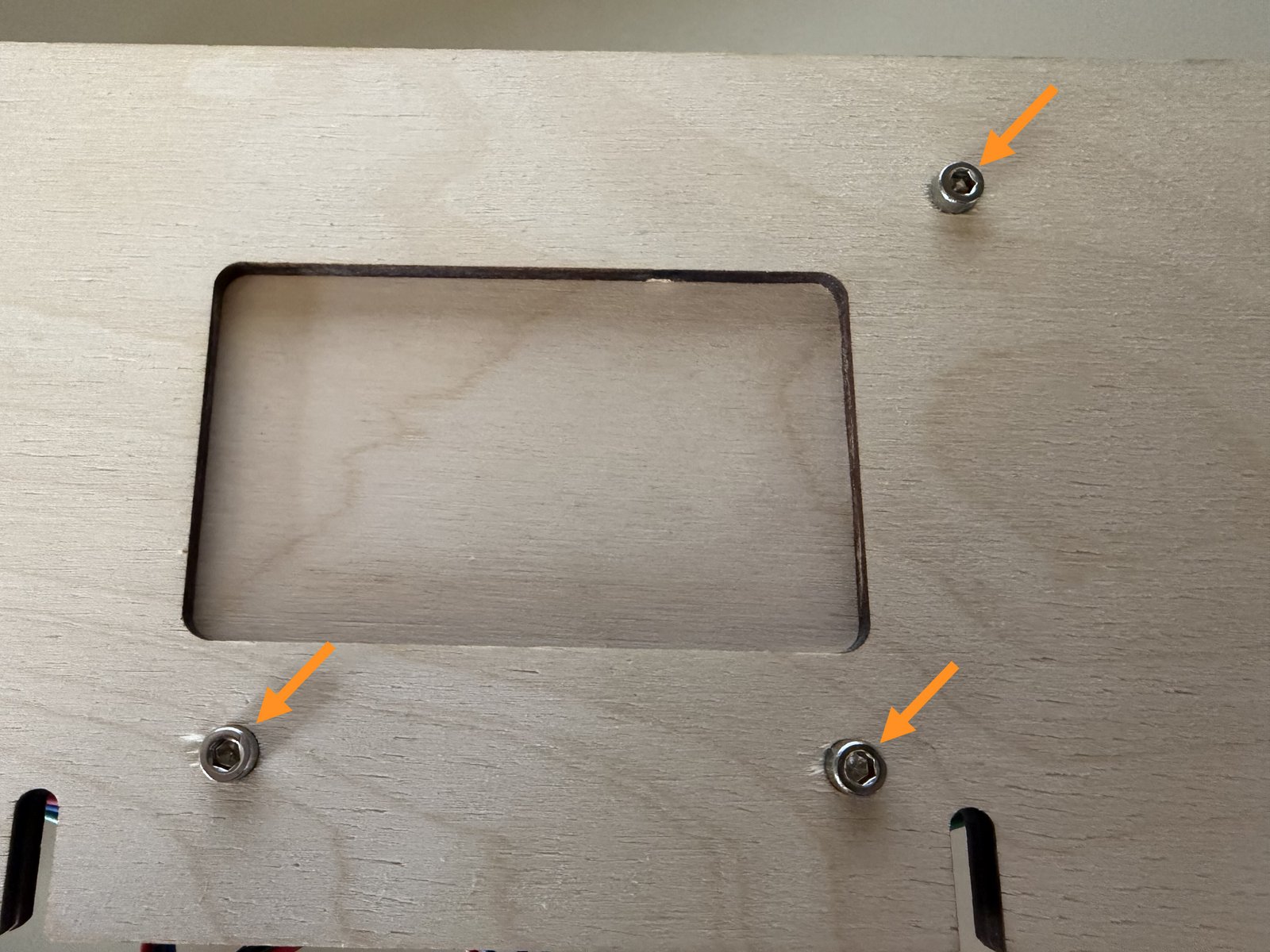
Click the large image to open full size.
In the center of the back plate are two cut out areas.
Around the left cut out are three holes for screws. In each hole, put one M3x10 screw back to front and an M3x25 standoff on the other side, facing the table.
Around the right cut out are three holes for screws. Into each hole put one M3x16 screw and two regular M3 nuts on the other side.
- Note:
It is easier to do this by feel without flipping the back plate over and over.
Step 6 Attach female DC power socket
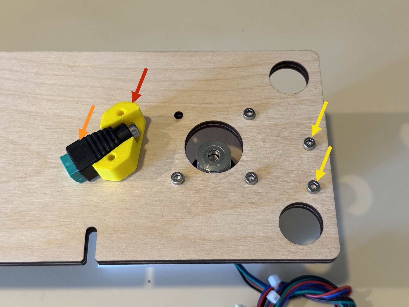
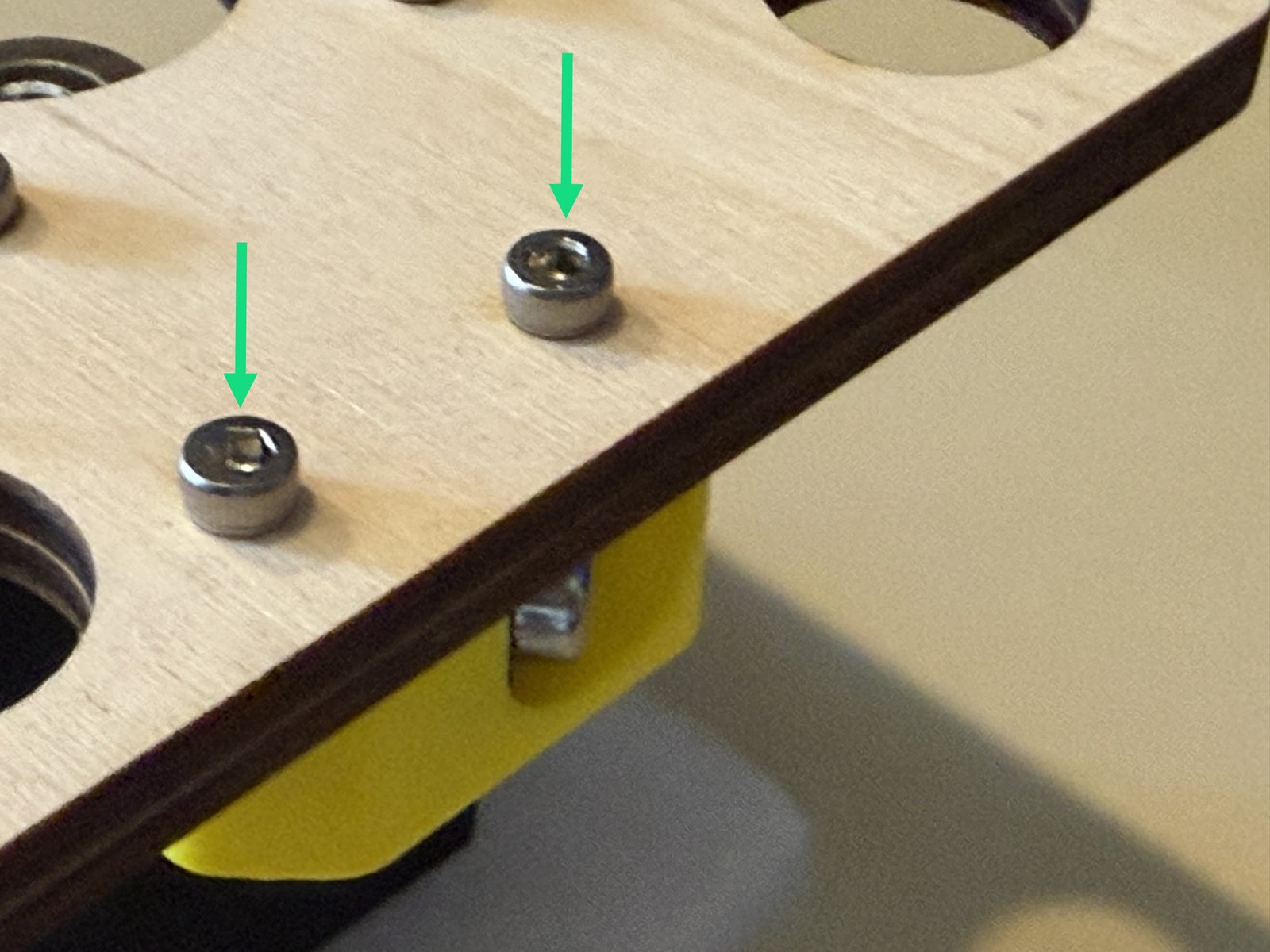
Click the large image to open full size.
Locate one mounting bracket;
One 5.5x2.1 female DC power socket;
and two M3x10 screws.
Without flipping the back plate attach the power socket on the right end of the back plate.
- Note:
It is easiest to line up the part while looking through the empty holes, attach one screw, and then do the other.
- Warning:
Make sure you don't attach it backwards.
- Warning:
When driving metal screws into plastic be careful to not over-tighten or it will strip the plastic and a new part will need to be printed.
Step 7 Unbox the LCD panel
Click the large image to open full size.
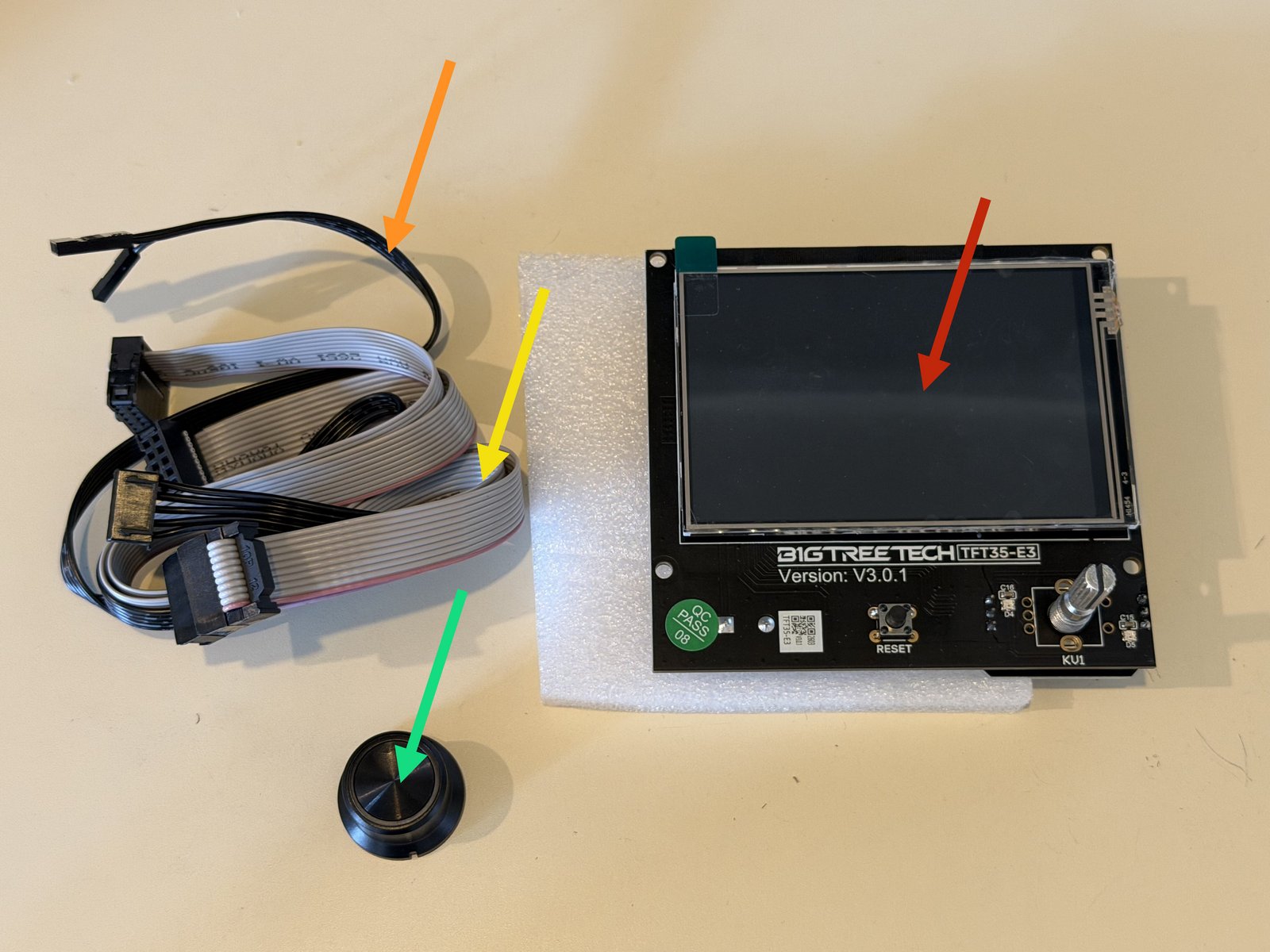
Locate the LCD box
Confirm it contains the LCD panel;
The black ribbon cable with one split end
The grey ribbon cable with one red edge
The dial
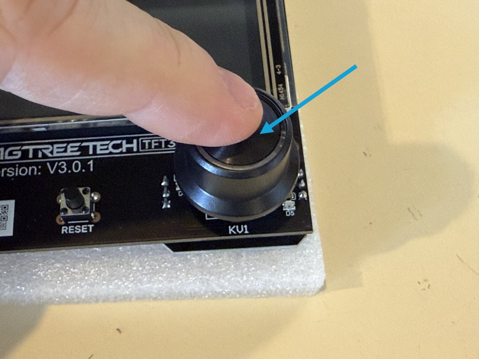
Firmly press the dial onto the potentiometer in the bottom right corner.
Step 8 Attach LCD cables
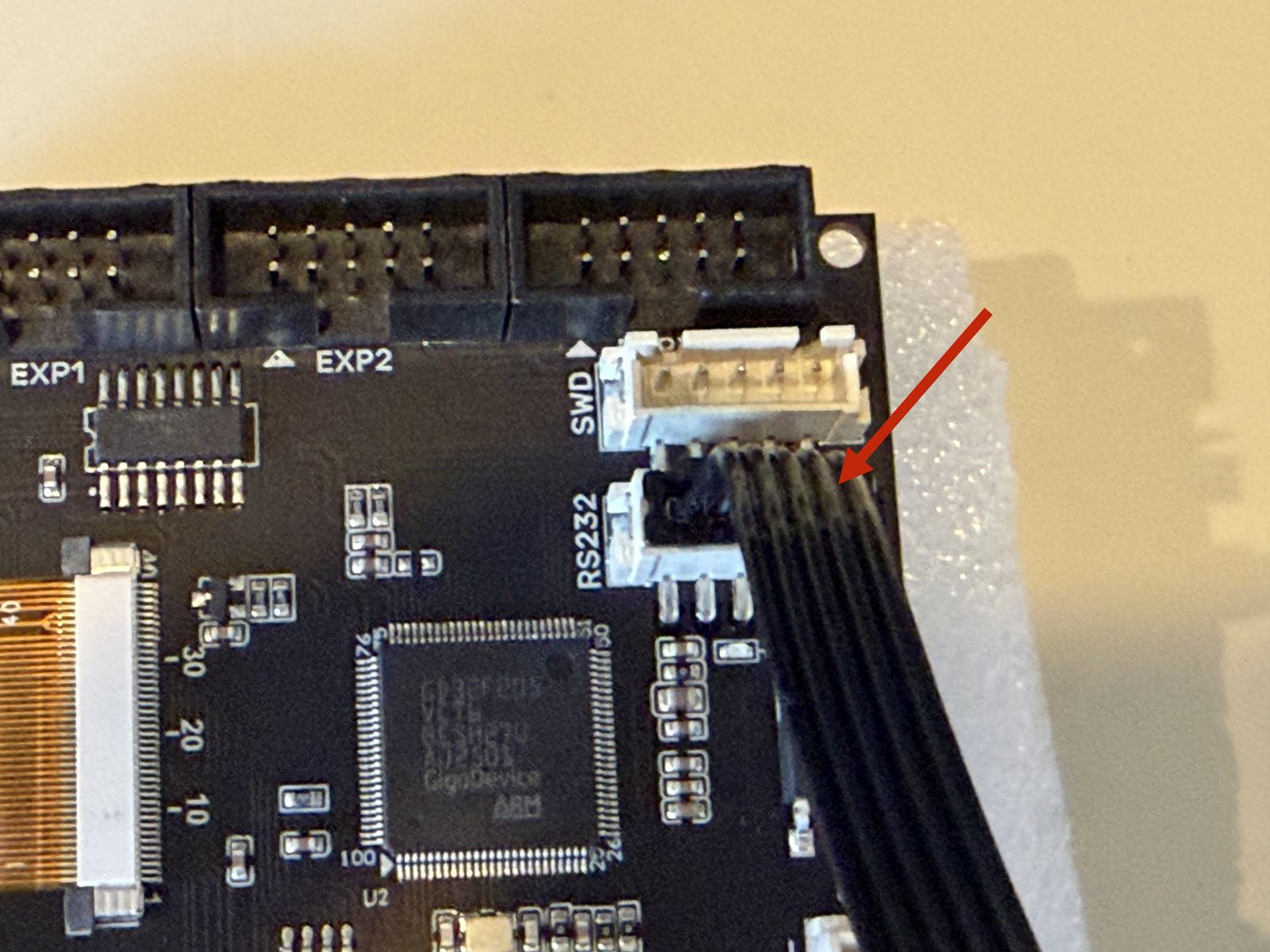
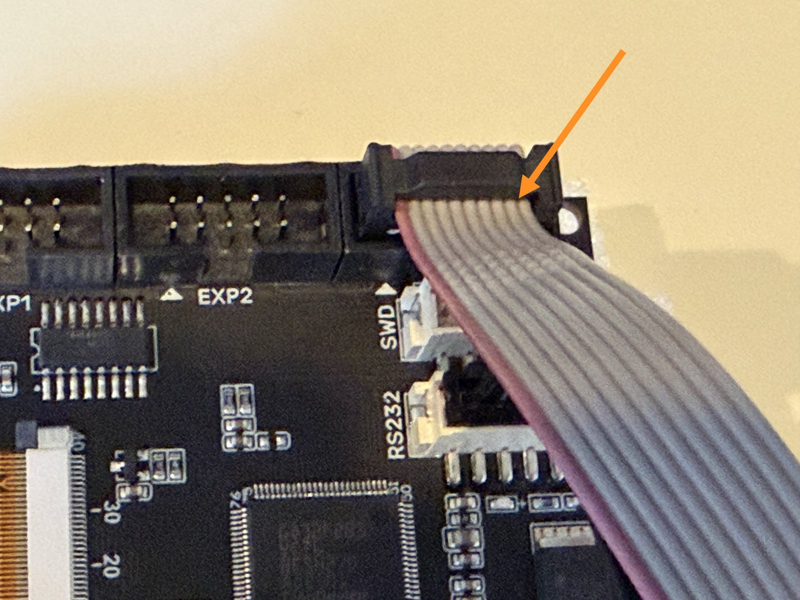
Click the large image to open full size.
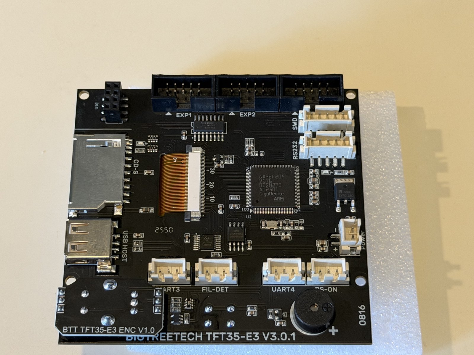
Flip the LCD over so that it rests on the foam that came in the box.
Attach the unsplit end of the black ribbon cable to the RS232 connector on the top right. It should only go one way and click into place.
Attach the ribbon cable to the EXP3 connector on the top right. It should only go one way, with the red stripe on the left.
Step 9 Prepare the control board
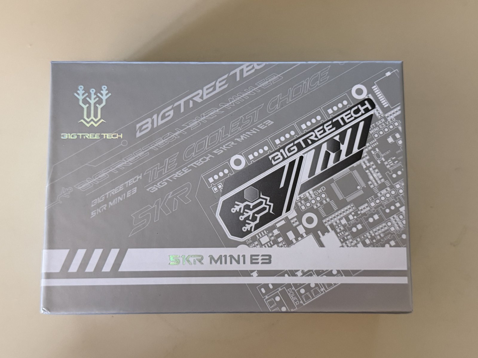
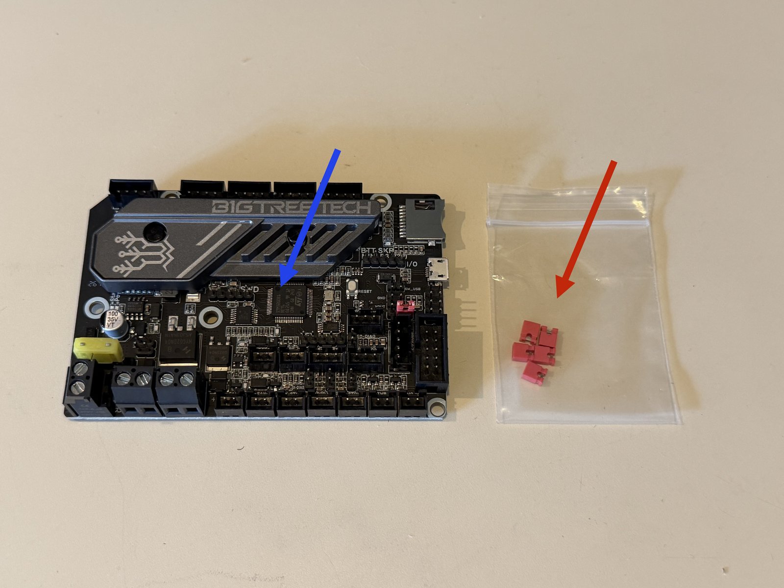
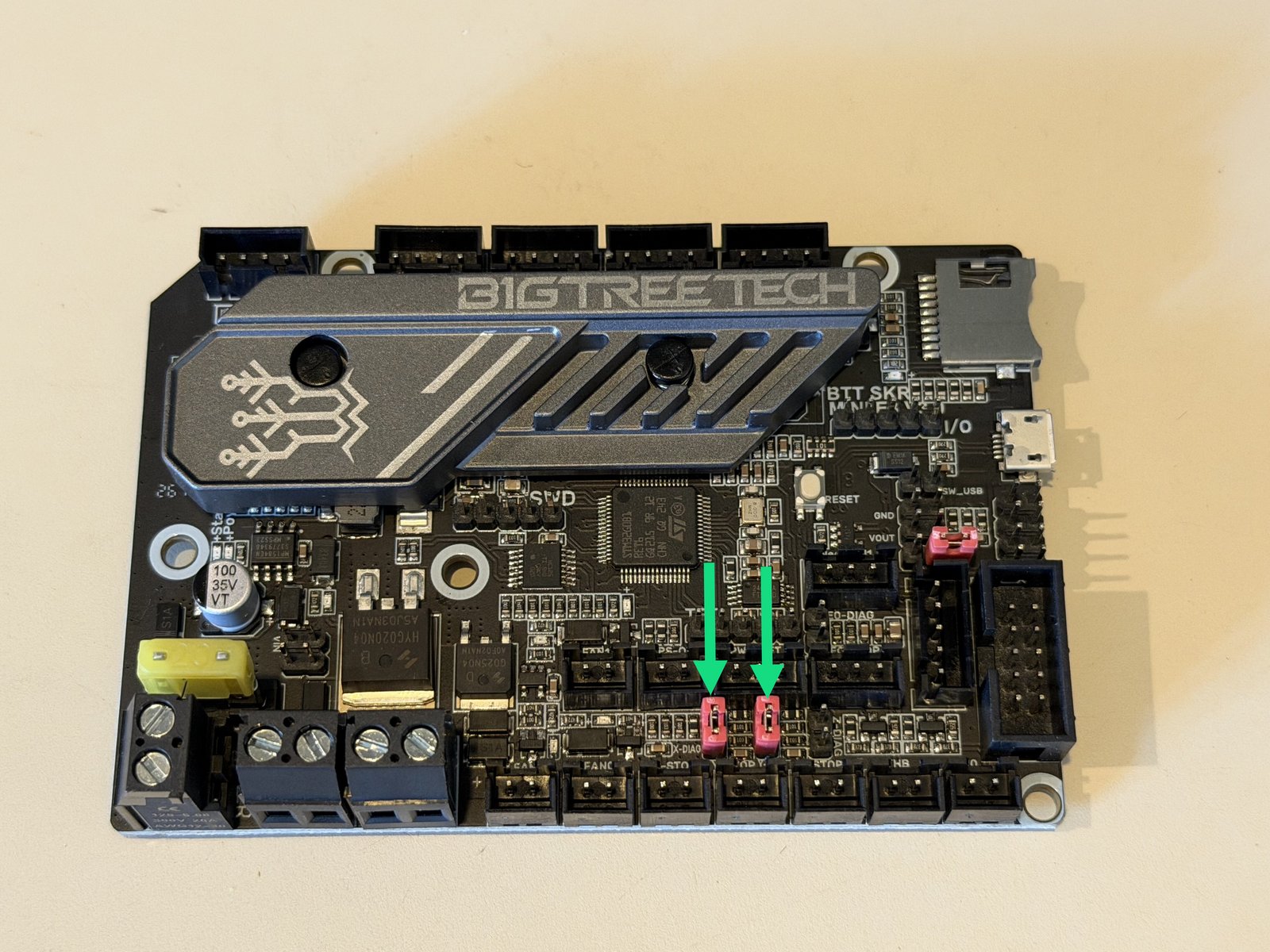
Click the large image to open full size.
Locate the Mini e3 box.
Confirm it contains the control board
and a bag of jumpers
Press the jumpers onto the pins for X and Y axis. These are the two sets of pins to the left. There is a third set of pins for Z axis that can be left empty.
Step 10 Attach the LCD and control board
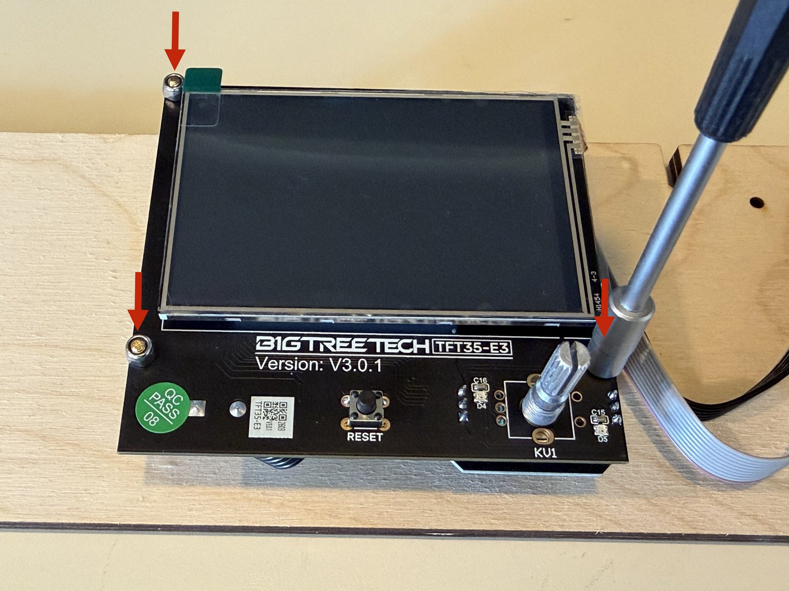
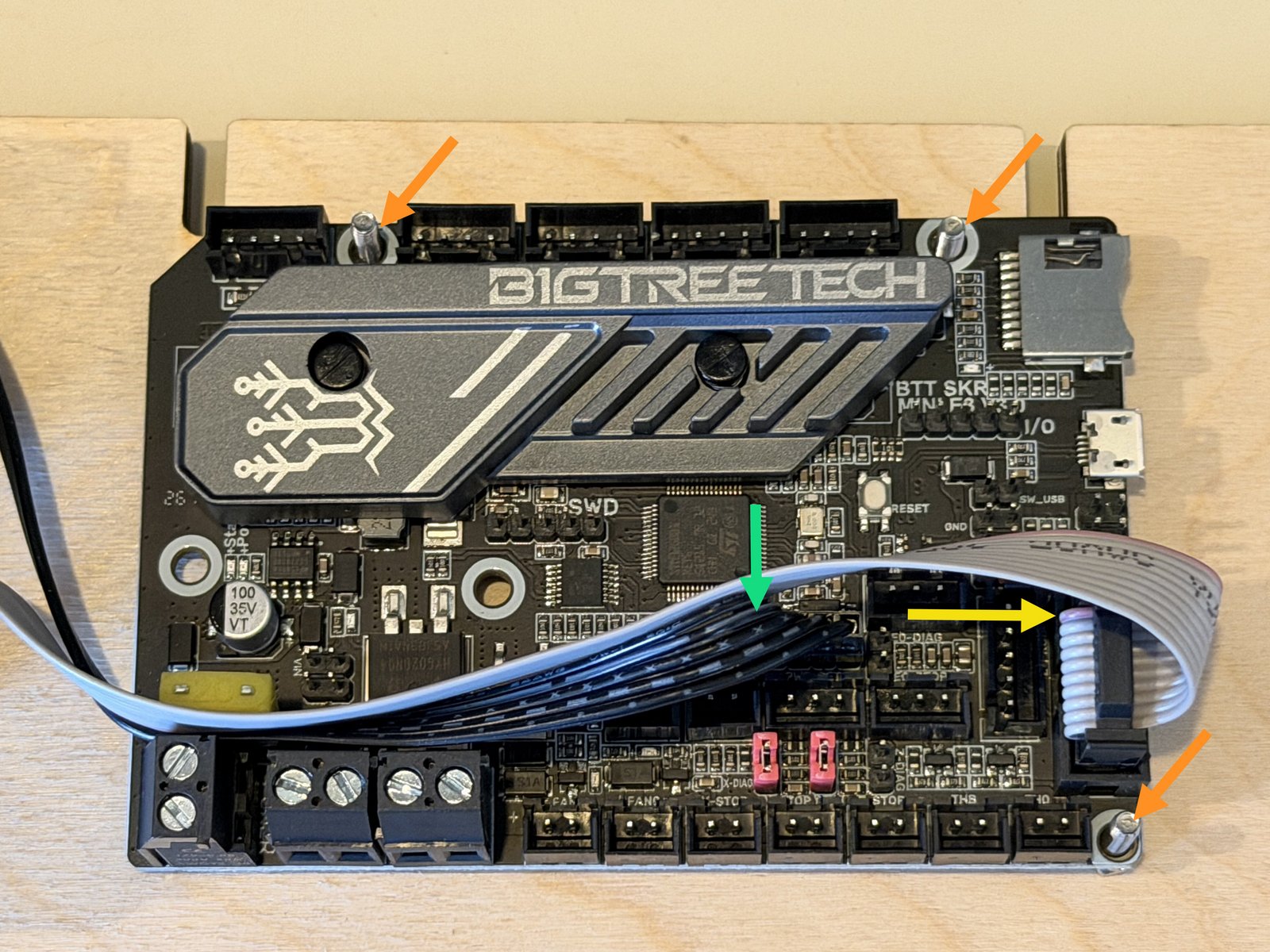
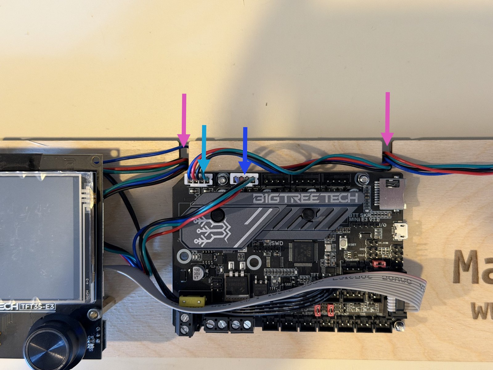
Click the large image to open full size.
Flip the back plate over.
Place the LCD panel on the three empty standoffs. Using an M3 socket driver affix the LCD with M3 nylock nuts.
Place the control board on the three M3x16 screws with the double hex nuts. Using an M3 socket driver affix the board with M3 nylock nuts.
Attach the black LCD ribbon cable to the TFT connector. The black ribbon cable on this end has 1-and-4 pins. The 1 pin is on the left.
Attach the grey LCD ribbon cable to the control board at the EXP1 connector. Make sure the red strip is on the top edge.
Attach the left motor cable in the left-most connector. It only goes one way.
Attach the right motor cable adjacent to the left motor cable, to the right of the top-left nylock. It only goes one way.
Weave the motor cables through the slots on the top of the board until they are not hanging loose.
Step 11 Connect the power
Click the large image to open full size.
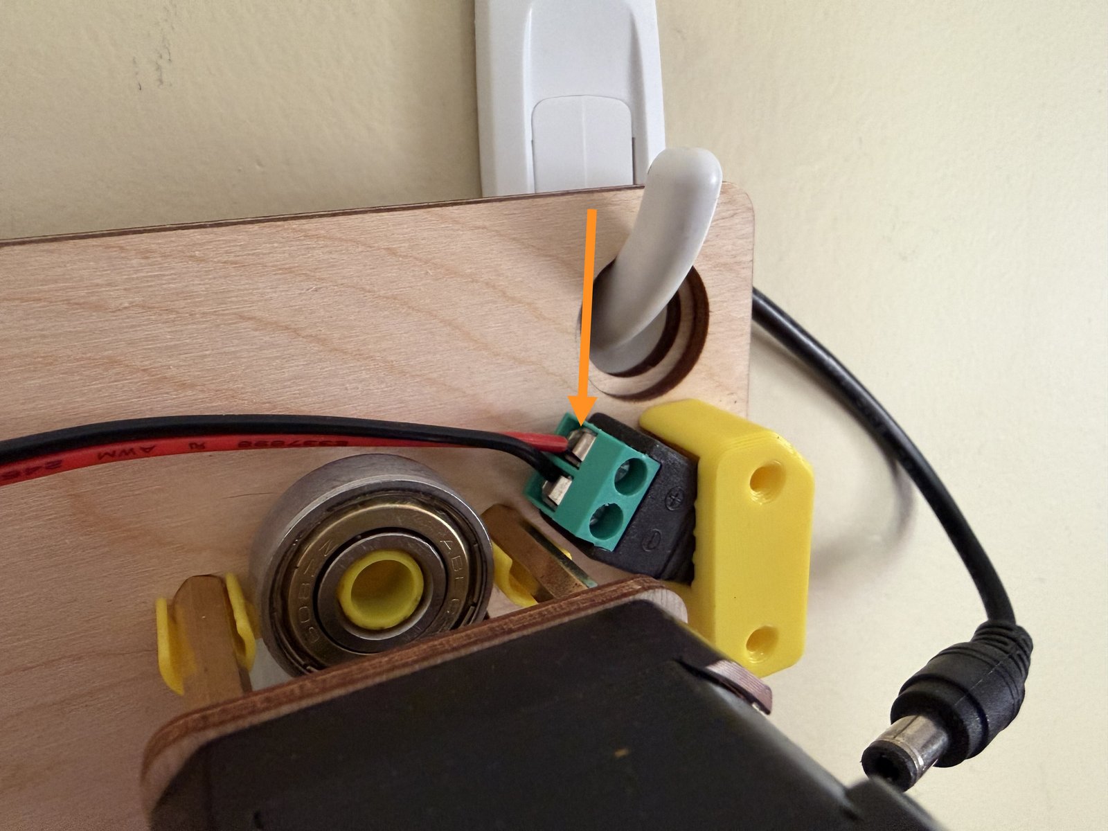
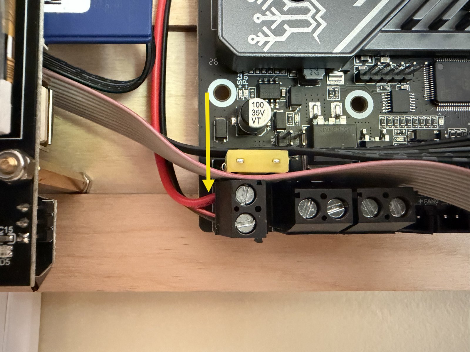
Cut a 42cm piece of 22 gauge hookup wire and strip 5-8mm from both ends.
Connect one end of the hookup wire to the female DC power connector on the right end of the back plate. Pay special attention to the + and - symbols on the connector. The red half of the hookup wire goes to +.
Connect the other end of the hookup wire to the terminal block on the bottom left of the control board.
Weave the power cable through the slots along the top of the back plate.
Complete
Congratulations! Now it needs firmware installed and a motion test before it can be certified and packed for delivery.