Robot Arm Tutorials

How would I create a robot arm from scratch?

Reddit user singdawg asked a great question:

I’m currently starting a project to [create a robot arm]. Anybody know good resources? I’m a capable programmer, have experience with microelectronics and microcontrollers. Have some advanced maths to understand the depth of material (jacobian matrices etc) but I’ve limited experience with servo motors.


If your goal is specifically to DIY a robot arm from scratch, I’d start by figuring out what are my design constraints. I’d choose a carrying weight limit, a reach distance, the number of DOF, and the maximum mass of each joint. from that I could build a kinematic chain to find my torque limits, and match those to available motors and gearboxes. Personally, I choose stepper motors. In Fusion360 I’d create models of those motors, then start placing them at their desired locations. The gaps between parts would be filled with my custom designs, which would then have to be manufactured. The custom design part is very iterative and very slow (for me). Some of the things I ask myself are: Where do the bearings and fasteners fit? How do I plan to make this custom part and how does that affect the design? Where do I run the wiring so it doesn’t catch and break? Have I remembered to put in *every* part, not just waved my hand and said “figure it out later”? Can I design this in smaller pieces for easier testing of each piece?

I should mention here that a robot built with stepper motors can’t tell where it is from moment to moment the way you or I can. Mostly they are built by having limit switches. The robot moves to touch the switches at startup. Since it knows where the switches are it can count steps as it moves from then on. It is crucial from that point on to never miss a step. One day we’ll have better encoders for DIY robot arms, but not yet!

Once I’ve reached a design I like, it’s time to use the bill of materials from Fusion360 to place my order for the parts, and get to making the custom bits while the orders are in the mail. Once they arrive I can put it together and figure out what I did wrong, then go back to the fusion custom part step 🙂

Once I get something that doesn’t fail on assembly, I take each major section of the arm in Fusion360 and save them out as STL files. I bring those into Robot Overlord and make it move virtually. I can then modify some Arduino CNC firmware to follow the same kinematic model that I used in RO, and now I have a GUI to drive it. There are several arms already in RO, feel free to branch it and add your own.

Robot Arm Torque Calculator

I find calculating forces boring and I love to code. So I wrote a Processing sketch that can simulate a robot arm enough to calculate some masses and torque values. My thinking is that I can use this to set an upper limit on the weight of each joint, then see the torque values and find the motors that will be under-weight and over-torque.

Robot arm torque calculator

The arm can be moved by clicking on a joint and pressing Q/E.  The values at the bottom are the joint number, the direction of rotation, the maximum weight, the distance from the previous joint, the current angle, and the current torque.  In a 6DOF arm there are joints 0-5 and joint 6 represents the weight of the tool or the payload carried by the arm.

Get and run the Arm torque calculator.

Final thoughts

I’ve done this with 3dof and 5dof arms. I’m currently working on a 6dof robot arm.  I like to design from the wrist backwards, because the payload is the most important part, and each motion after that depends on the ones that come before it.

I’m constantly distracted by the work of assembling my other machines. Ironic! If I had the arms they would do the work for me. Soon, soon!

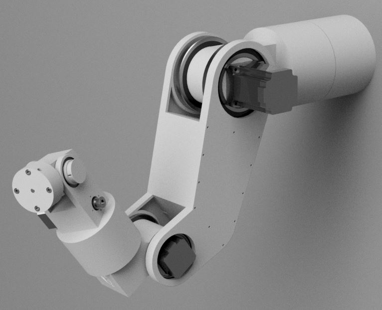
Next in part 2 I will show some of my work designing the arm based on the calculated constraints.

Tutorials

Build your own falling block game like Tetris

I’ve shown you how to use shift registers to drive an LED grid, including how to draw pictures on the screen from memory. Now we’re going to use those tools to make a game similar to the classic Tetris.  I’ll show you the circuit, how to draw pieces, how to create animations, respond to user input, and more.  Learning how to build complex behavior from simple parts is a great start to thinking about how robots behave.
https://www.instagram.com/p/BRMLTCeAd7y

(more…)
News

Reykjavík University Stewart Platform controlled by a DIY joystick

Kristófer Reykjalín shared a video of a Rotary Stewart Platform v2 driven from a home made joystick. A student group studying Mechatronics at Reykjavík University in Iceland used the Stewart Platform to demonstrate what they’ve been studying about control theory.

The team included Kristófer Reykjalín Þorláksson, Haukur Hlíðberg, and Stefán Óli Valdimarsson. Their professor is Joseph Timothy Foley.

Their code is uploaded on Github. Kristófer says the design files for the joystick will be there soon, too are also part of the Github package.

News

Big Mess of Wires, the DIY 8-bit CPU

Big Mess Of Wires

If you ever get sick of modern computers, you can always restart from scratch and build your own CPU. There’s even a group of enthusiasts online who do that just for fun. They’re so fond of old tech they still have a web ring. Hello, 1995!  You make me feel young again.

I think my favorite part of Steve’s incredible work is this quote from his project goals: “Keep the hardware complexity to a minimum. I’m not an electrical engineer.”  Which is funny, because the voices in my head say “I couldn’t do that even if I was an electrical engineer.” and then “Not with that attitude.”  Steve is a great example of willpower put into action, my friends.  On a long enough timeline that’s all it takes, like Andy Dufrane digging that tunnel in <i>The Shawshank Redemption</i> or going to the moon.

For all the schematics, design plans, and encouragement check out The Big Mess Of Wires.

Tutorials

How do I choose controller electronics for my first CNC?

Tony asks “How do I choose controller electronics for my first 2D DIY CNC?”

What’s a CNC?

The Makelangelo, Delta robots, Stewart platforms, robot arms, CoreXY CNCs, and traditional CNCs are all fundamentally the same.

A CNC is a Computer Numerical Control device, a machine for moving precisely in one or more directions. A CNC machine needs (at least) one motor for each axis (direction of movement). All the motors are controlled by an electronic circuit. The motors and the circuit use a power supply to create the motion you want. The circuit may also need sensors to stay calibrated and do the job right. The circuit also needs to follow your programmed instructions. Put another way, your circuit needs to support your software, your motors, your power supply, and your sensors.

Electronics

Here are some examples of circuits available.

Arduino is a really popular and well supported platform for learning to build robots, including CNC machines. This is the part of the machine that you program with your instructions.

The Adafruit Motor Shield v1 stacks on top of an Arduino and makes it easy to run two stepper motors and a two servos and some switches for homing. This is a great starting point at an affordable price.

There’s also the RUMBA board. It runs 6 steppers, one servo, and 6 switches.  That’s the high end board for a 3d printer or a Stewart Platform.  It has an Arduino built in.  It is much faster than the AMS1.

Stepper motors

For your first machine, use stepper motors. Stepper motors turn one step at a time, typically 1.8 degrees (200 steps per turn). The math and the control system easy to build, compared with other kinds of motors. Stepper motors come in many shapes, sizes, and power levels, like the NEMA17 0.3a 12v steppers. Stepper motors can also use microstepping to split each step into (as many as) 32 sub-steps.

Servos

Servos are commonly used in Radio Controlled toys. A servo turns like a stepper motor, but it doesn’t turn one step at a time. Using a signalling system called PWM you can tell a servo what angle you want and it goes to that angle as fast as it can. Typically servos are accurate to within 5 degrees, so using them in a CNC depends a lot on your application.

[products skus=’MOTO-0002, ELEC-0046′]

Power supply

Your power supply keeps everything running. All the boards mentioned above run on 12v. The power supply amperage must be GREATER THAN the controller amperage.

For the AMS1 I’d suggest a 12v power supply and 5.5 x 2.1 female power plug.

[products skus=’ELEC-0001, ELEC-0007, ELEC-0042′]

For the RUMBA board I would suggest a 650w power supply from a PC. It has multiple 12v and 5v lines to give you lots of everything.

Sensors

Your limit switches will prevent the machine from moving too far and hurting itself. With switches the machine can always return to the same starting spot, even if it gets turned off. that way you can restart or repeat a job. For a 2 axis machine you want two to four switches.

Final thoughts

Discuss your plans in our forums and we’ll be happy to help you with selection, assembly advice, and more.

Marginally Clever stands committed to helping you succeed. Ask us anything about our products, we’re happy to help.

See Also